|
|
|
|||||||||||||||||||
|
The Prototype Märklin-H0-Knowledge Layout-Building Modelstock |
|
|||||||||||||||||||
|
A: The
very first basic knowlege about conventionally controlled Märklin H0 model
railways A19:
Siding tracks — parking spaces for locomotives and wagons |
|
|||||||||||||||||||
|
The
original question that led to this article was: How
do I make the locomotive stay on the siding while I run another one? It
has turned into a substantial piece. Contents: A) The switchable siding —
simplest installation. E) The assignment of the
track zones to the controllers (manual assignment switching) H) Electrical circuits with
signals Let's
go... You
also need: 1st
a center conductor insulation (depending on the type
of track, see article "Driving with several transformers...") 2nd
a power feeding track and 3rd
a control panel (see article "The Evolution of Märklin
command and switch panels") or another switch for switching
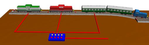
on and off. The
installation location of the centre conductor insulation is marked in the
picture with an insulation sign "Märklin 5015".
After
installation of the insulation, the siding is de-energised. A
locomotive only moves so far into the track as long as its slider has contact
with a stut contact BEFORE the insulation. If
the slider is completely on the insulated stut contacts, it stops. In
order to be able to drive inside the insulated track, you have to install a
power feeding track there. This
siding is not connected directly to the transformer, but a Märklin switch
panel or a switch from the accessory trade is installed in the red line. The
brown earth line is connected directly to the transformer.
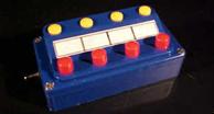
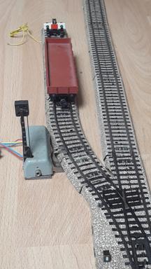
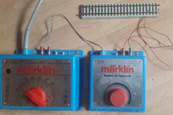
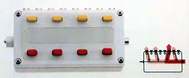
The
control panel shown here is a "Märklin 7210" (1962 - 1994).
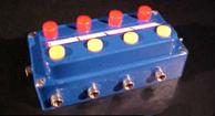
The
predecessor "Märklin 475/4" (1950 - 1956) or "7070" (1957
- 1961) can be used too…
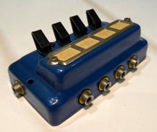
...
or one of the newer switchboards "Märklin
7274" (2000 - 2004) or "Märklin 72740" (2005 - today).
Disadvantage of this simplest circuit If
a locomotive is parked in a siding and a wagon with a slider is pushed into
this switched-off track, the slider bridges the isolation and the parked
locomotive moves. A
— not optimal — solution for this is an additional piece of track at the
beginning of the siding that can be switched off and is longer than the
longest slider.
It
is better to divide the siding into several zones by insulating the center
conductor in several places and installing several power feeder tracks. This
way you can then park one or more locomotives and still park wagons — even
with sliders — in front of them.
The
brown connection lines are all combined. The installations described so far are the minimum. On the subject of sidings, however, I have thought of much more.
That's what the rest of this page is about. In
order to describe the things related to sidings in a clear way, I have
constructed a (small) example. I
hope that you can draw conclusions from it for your own layout. In
the course of the development of this article, further thoughts and ideas
have constantly flowed in, so that the track plan and the details have become
somewhat more complicated than originally intended. The
descriptions are intentionally as detailed as possible so that as much
expertise as possible is conveyed. |
|
|||||||||||||||||||
|
B) Definition of
"siding” A siding,
in rail terminology, is a low-speed
track section distinct from a running line or through route such as a main line, branch line, or spur. |
|
|
||||||||||||||||||
|
A siding is a track — often a stub track — used to
accommodate rail vehicles that are not needed. This can range from a few hours'
storage to the permanent parking of decommissioned vehicles. Sometimes this is also understood to
mean tracks for train formation, often parked
passenger trains are also cleaned or preheated here. Sidings are not used for train
movements beyond the station and are therefore considered non-main tracks. The following are not considered as sidings ·
Platform
sidings where trains are parked for boarding and alighting, ·
loading
sidings for loading and unloading, and ·
evade and
passing sidings where one train waits for another. If the stub track is not only used for
parking but also for turning trains, i.e. turning for the return journey on
the other track of a double-track line, this track is also called a reversing
track. Track boundaries A siding begins behind a turnout. A siding ends before a second
turnout or at a buffer stop or similar obstacle
that is suitable for stopping a slow-moving wagon in an emergency. Track spacing If the siding is intended solely
for parking and not for any treatment of the vehicles, the track spacing may
be relatively narrow. If the siding is used for work on
the vehicles, the distance to the next track must be large enough for people
and equipment to have sufficient and safe room to move. |
|
|||||||||||||||||||
|
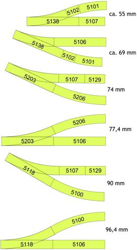
The type of turnout determines the
track spacing. (Examples with M-tracks, |
|
|
||||||||||||||||||
|
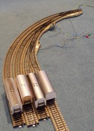
Extreme and negative example: THAT is possible, but definitely
too narrow. |
|
|
||||||||||||||||||
|
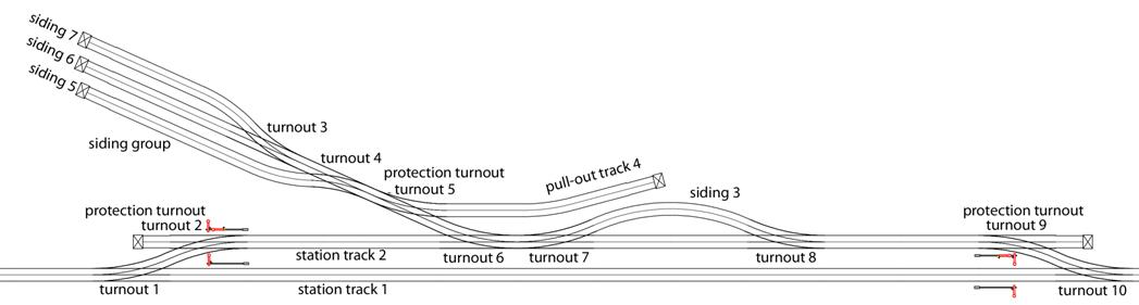
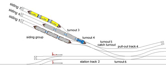
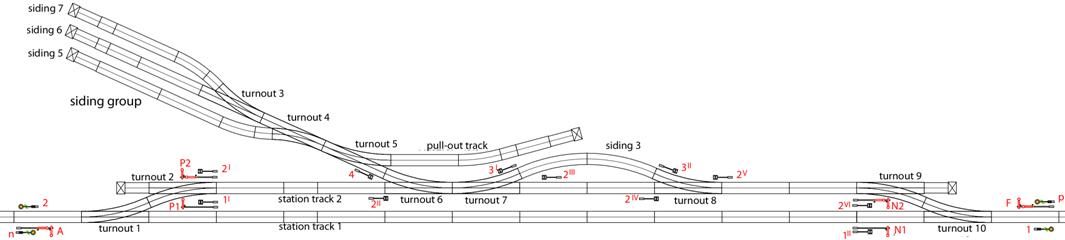
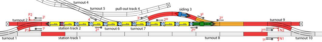
My “small” example: C) A siding facility
at a station. This can be a local goods station
or also a works siding. We disregard the signals for the
time being to keep the description and circuit simple. |
|
|||||||||||||||||||
|
|
|
|||||||||||||||||||
|
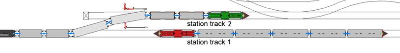
What was I thinking about? Station track 1
is the through track of the single-track line. Through trains remain on station
track 1. If station track 2 is free, a train waiting on station track 1 can be overtaken or an oncoming train can be let past, the
expert says: the trains "cross" (taken from German, correct in
english?). |
|
|||||||||||||||||||
|
|
|
|||||||||||||||||||
|
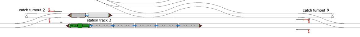
Station track 2
is therefore used for train movements, but also for shunting. Since individual wagons or groups of
wagons without locomotives are occasionally parked on station track 2, this track is closed off from station track 1 by "catch turnouts", turnout 2 and turnout 9. |
|
|||||||||||||||||||
|
|
||||||||||||||||||||
|
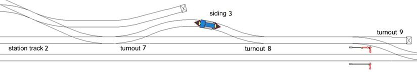
Siding 3
for a shunting locomotive is connected to station track 2
with turnout 7 and turnout 8. It can also be used for shunting individual wagons. The
slightly longer piece of track between turnout 8
and turnout 9 is used for this operation. |
|
|||||||||||||||||||
|
|
|
|||||||||||||||||||
|
A siding group with three sidings 5, 6 and 7 and a pull-out siding 4
branches off from the station track 2 with
turnout 6. When the shunting unit is completely
behind turnout 5, this can be switched to
pull-out track 4. Turnout 5
then serves as a catch turnout against unintentionally departing wagons. |
|
|||||||||||||||||||
|
|
|
|||||||||||||||||||
|
The wagons that are to enter the
siding group have previously arrived as a train journey in station track 2. After the train movement has officially
ended in front of one of the main signals at station track 2, the train set or parts of it become a shunting unit. It is irrelevant whether a shunting
locomotive or the train locomotive performs the shunting operation. Pulling the train locomotive and
bringing a shunting locomotive can be defined as shunting operations inside
the station or as train movement (locomotive train) from/to outside. |
|
|||||||||||||||||||
|
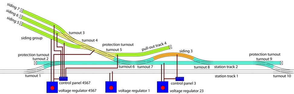
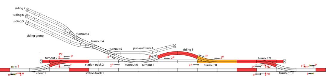
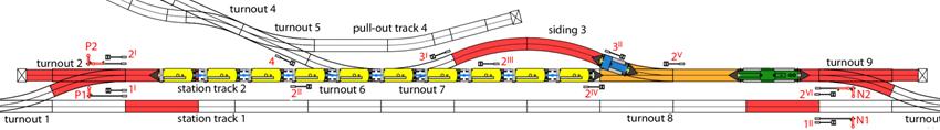
D) The driving
voltage zones — minimum
circuits without signals (manual section switching and transition
circuit)
|
|
|||||||||||||||||||
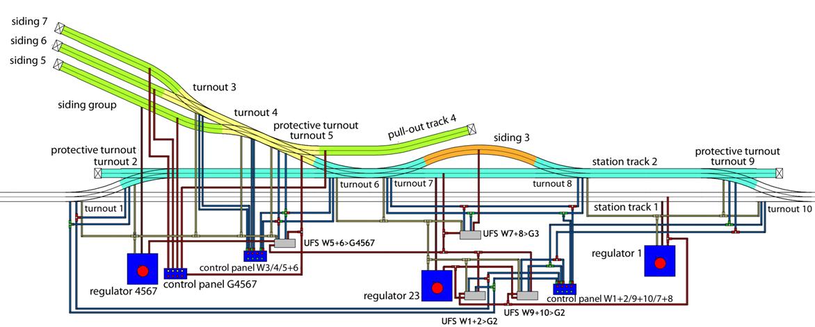
|
Controller 1
of the through line still retains its purpose. Station track 2
(blue) and siding 3 (orange)
get their own controller 23. The siding group (yellow and green,
tracks 4, 5,
6 and 7
with connecting turnouts) gets its own controller 4567,
so that the station track 2 (blue) can
continue to be used independently, while shunting takes place in the siding
group. The earth connections of all
controllers are connected via the rails. The centre conductors are insulated
at all points where the track sections change colour in the track plan above.
For siding 3,
the running voltage is connected to controller 23
via a switch on control panel 3. The centre conductors of the green
tracks 4, 5,
6 and 7
are connected to controller 4567 by means
of the switches of the control panel 4567. Section
switching: Disadvantages of this
simplest circuit 1st
disadvantage: If a locomotive is parked in a siding and a wagon with a slider
is pushed into this switched-off siding, the slider bridges the insulation
and the parked locomotive moves. See above. 2nd
disadvantage: You have to work with two controllers when the locomotive
changes the area. (transition circuit) Transition
circuit: Remark: I am talking about
"controllers" here. |
|
|||||||||||||||||||
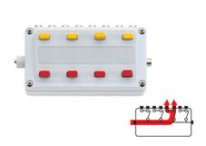
|
For example the Märklin controllers
6600 and 6699 are only controllers, they do not contain transformers, but
they are connected to transformers and are advantageous in shunting when
running very slowly (NOT with digital locos). |
|
|
||||||||||||||||||
|
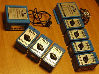
For example, under the brand
"TITAN" there were transformers for which there were additional
controllers to plug in.
Attention: If you use several transformers at the same
time, see the article "Driving
with several transformers — danger due to incorrect connection"! |
|
|||||||||||||||||||
|
E) The assignment of
the track areas to the controllers (manual assignment switching)
|
|
|||||||||||||||||||
|
Manual changeover switches are not
a Märklin product.
To move from station track 1 (white) to station track 2
(blue), you set the change-over switch R1 ‑ R23 to controller 1. Assignment
switching: For the journey from station track 2 (blue) to the siding group (yellow) set the change-over
switch R1/R23 ‑ R4567 to R1/R23. With this circuit you can drive
from the track to the siding with controller 1,
if you set the change-over switches this way. It is also possible to couple this
switch with the turnouts. However, this is rather a topic for
advanced users, but I will show it here anyway... |
|
|||||||||||||||||||
|
F) Automatic
circuits of the controllers between the tracks areas depending on the
turnout’s positions. (automatic assignment switching)
|
|
|||||||||||||||||||
|
The functions of this circuit: 1st:
controller 1 always operates the white
track, i.e. the mainline tracks and station track 1. 2nd:
controller 23 operates the blue track when
turnouts 1 and 10
are both straight ahead (see 1st). (Turnouts 7
and 8 are switched together in this
circuit, both straight or both branching. 3rd:
Controller 4567 operates the siding group
when turnout 6 is straight and turnout 5 is branched. 4th: The running
voltages of tracks 4 to 7 are switched on and off manually. Description of the
components: 4 universal remote switches
"Märklin 7045" are used here for automation (7245 and 7244 also
work, of course, or bistable relays of other brands. See article "The
relatives of the Märklin universal remote switch"). Controller 1
primarily feeds the line tracks left and right and the station track 1. Additionally a red wire leads from
its connection B to the two universal remote switch W1+2>G2 (the designation means turnout pair 1+2 controls
supply of track 2) and If turnout pairs 1+2 and 9+10 are even,
controller 1 applies to the mainline and
station track 1 and controller 23 applies to station track 2
and, depending on turnouts 7 and 8, siding 3. If the turnout pair 1+2 or/and the
turnout pair 9+10
is/are branching, controller 1 applies to
the mainline and the station tracks 1 and 2 (and the siding 3). The turnout pairs 1+2 and 9+10 are set
independently of each other via one button pair each of the control panel W1+2/9+10/7+8. If the turnouts 7 and 8 are
branched off, track 3 is supplied
by the same controller that is currently responsible for track 2. Turnouts 6
and 5 are switched together in the
opposite sense via a pair of buttons on the W3/4/5+6
control panel: Turnout 6
branching and turnout 5 straight or
At the same time, the universal
remote switch W5+6>G4567 is switched so
that the siding group is supplied by the same controller that is currently
responsible for track 2 when
turnouts 6 and 5
point into the siding group, or by controller 4567
when turnouts 6 and 5
block the track connection. With the control panel 4567 the pull-out track 4
and the sidings 5, 6 and 7 can be
switched on and off individually. The yellow power supplies for the
turnout lanterns and the universal remote switches are connected to the
nearest controller in the plan (connection L). The brown earth wires are routed
here in a straight line to the track(area) for which
the controller is intended. Why, when and where do signals have
to be placed at the siding in the prototype? Whether the passing of the turnout
is controlled by signals depends on the operational conditions: If the turnout does not lead into a
track controlled by the signal tower and is set by the shunter on site, no
signals are necessary. If the turnout is set by an signal
tower, protection signals or wait signals belong at all three approaches, the
locomotive driver must follow the instruction of the signal tower: |
|
|||||||||||||||||||
|
o
a switchable protection signal Sh0/Sh1 as a form or light signal (Märklin calls it a
track blocking signal, see the article "Märklin H0 Signals —
purpose and function"). |
|
|
||||||||||||||||||
|
o
a wait signal Ra11 in the area of
the Federal Republic of Germany before 1990 and Ra11a in the area of the
former GDR.
Wait signals were never in
Märklin's programme. There are suppliers who offer wait signals that are very
true to the original. There are waiting signals as simple "sheet
metal" signs and also with lighting and/or as a combination with the
light signal Sh1. |
|
|||||||||||||||||||
|
At the end of a stub track there is
usually a protection signal, usually to the right of the track, but also
sometimes on the buffer beam. |
|
|||||||||||||||||||
|
At a siding there is usually the
protection signal Sh0. At a stub track, where train
movements end, there is usually the protection signal Sh2. |
|
|
||||||||||||||||||
|
At night, a protection signal may
be illuminated, Sh2 may be
replaced by a red lamp or a red lamp may be integrated in the sign. This marks the end of the permitted
usable track area. |
|
|||||||||||||||||||
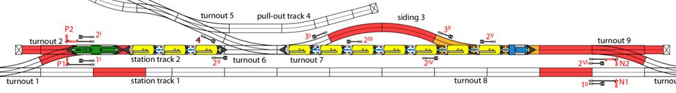
|
The track plan then looks like this
with signals: The designations of the tracks,
turnouts and signals follow the usual Deutsche Bahn rules for station tracks. |
|
|||||||||||||||||||
|
|
|
|||||||||||||||||||
|
A station begins at the entrance
signals A and F.
The approach signal n at the Esig A announces
the position of one of the exit signals N1 or N2, depending on the turnout’s position, depending on the
route. Recommendation: For understanding
please read the article "Märklin signals —
purpose and function". Station track 1
is the continuous track of the single-track line. Station track 2
is used for train movements and also for shunting movements. Protection signals are numbered
with the track number and counted through with superscript Roman numerals in
kilometre counting direction. It would be correct to place
protection signals between turnouts 6 and 7 in both directions. Track 3
is protected at both ends with protection signals 3I
and 3II. The siding group is secured with
protection signal 4. H) Electrical
circuit with signals We assume that all turnouts and
signals are operated individually or in functional connection via control
panels. The coloured track sections are
connected to the train control of the neighbouring signals and are
temporarily without running voltage. |
|
|||||||||||||||||||
|
|
|
|||||||||||||||||||
|
An arriving train that is to be
dismantled here must first pass one of the entrance signals A or F. With Hp0 = stop
commanding entrance signal, the red track in front of it is de-energised due
to the "train control" (see article "Märklin signals —
purpose and function") and the train stops. The distant signal n at the entrance signal A
is connected to one of the exit signals N1 or N2 via a universal remote switch according to the set
route and signals synchronously with it. The distant signal p at the entrance signal F
is connected to one of the exit signals P1 or P2 via a universal remote switch according to the set
route and signals synchronously with it. The circuits of distant signals at
entrance signals is described in the article
"The single-track main line — controlling two-way traffic with
signals". A shunting locomotive is parked in
siding 3. You can put turnout 7 with protection signal 3I
on the same control desk contact, as well as turnout 8
with protection signal 3II.
If the arriving train comes from the left, If the shunting locomotive from
siding 3 is to take over the shunting job,
the train must stop in front of exit signal N2
in such a way, that turnout 8 is free
after the removal of the locomotive. |
|
|||||||||||||||||||
|
|
|
|||||||||||||||||||
|
When the way and the stopping point
have been set, the protection signals 2II
and 2IV are set to Sh1 = driving ban lifted, and then the entrance signal A is set to Hp2 = slow running
and the train enters station track 2 from the
left. The train passes the exit signal P2, which shows Hp0 = stop
for the opposite direction, and the protection signal 2I,
which shows Sh0 = stop! No driving for the
opposite direction. Because the turnout 1 points to station track 2
and the entrance signal A commands Hp2 = slow speed (these are the conditions), this track
section is supplied with traction voltage via a universal remote switch, so
that the train can pass the signals. The circuit for passing a signal
showing stop in the opposite direction is described in the article "The
single-track main line —
controlling oncoming traffic with signals". The train reaches the exit signal N2, which shows Hp0 = stop,
and stops in the red or orange track in front of the signal. The just passed entrance signal A is set to Hp0 = stop. The exit signal N2 officially ends the train journey here. If the shunting locomotive from
siding 3 is to take over the shunting job,
the train’s locomotive uncouples and goes forward to exit signal N2 by switching the orange area back to the general supply
of the track. If the locomotive is to carry out
the shunting job, it remains coupled to the train. |
|
|||||||||||||||||||
|
|
|
|||||||||||||||||||
|
When the arriving train comes from the right, turnout 10
and protection turnout 9 are set to
branching, protection turnout 2 and turnout
1 are set to straight and turnouts 6, 7 and 8 are set to straight. When the track is thus set, the
protection signals 2V
and 2III are set to Sh1 = driving ban lifted, and then the Esig F is set to Hp2 = slow running,
and the train enters station track 2. The train passes the exit signal N2, which shows Hp0 = stop
for the opposite direction, and the protection signal 2VI,
which shows Sh0 = stop! No driving for the
opposite direction. Normally, the red track of these signals would be
de-energised. Because the turnout 10 points to station track 2
and the entrance signal F commands Hp2 = slow speed (these are the conditions), this track
section is supplied with traction voltage via a universal remote switch so
that the train can pass the signals. The train reaches the exit signal P2, which shows Hp0 = stop,
and stops in the red track in front of the signal. The just passed entrance signal F is set to Hp0 = stop. The exit signal P2 officially ends the train journey here. |
|
|||||||||||||||||||
|
|
|
|||||||||||||||||||
|
If the shunting locomotive from
siding 3 is to take over the shunting
service, turnout 8 must be
free. The locomotive is uncoupled and can
wait here if it is to take over a new train here, or be sent back on the
track as a locomotive train. If the locomotive is to carry out
the shunting work, it moves from the left end of the train via track 1 as a blocking run to the right end of the train. |
|
|||||||||||||||||||
|
|
|
|||||||||||||||||||
|
For a shunting run, the protection
signals on the route in the direction of travel must be set to Sh1 = driving ban lifted. The (shunting) locomotive pulls the
train or a part of it to the right until turnout 6
is free. If there is no locomotive in the protective track at turnout 9, the train can be pulled to the buffer stop if the
protection signal 2VI
is set to Sh1 = driving ban lifted and
thus the red track area becomes passable. If it is regularly necessary to
drive into the red track area BEFORE the protection signal 2VI, but not past the signal, the track section
in front of the signal (but not turnout 9) can be
supplied with traction voltage via a switch, just like the orange area. When the shunting unit has cleared
turnout 6, the protection signals 2II and 2III
are set to Sh0 = stop! No driving. Then
turnout 6 is set to branching and protection
turnout 5 straight and turnouts 3 and 4 as required
and then protection signal 2III
is set to Sh1 = driving ban lifted again. The protection signals 2II, 2III,
2IV and 2V have no electrical influence on driving.
They are set up for regulatory reasons and must therefore be set and
observed. |
|
|||||||||||||||||||
|
|
|
|||||||||||||||||||
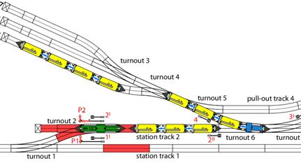
|
The locomotive pushes the shunting
unit into the target track. If the shunting unit is longer than the target
track, it is separated at a suitable point and the locomotive pulls the rest
back. Turnouts 3 and 4
are set as required and the rest of the shunting unit is pushed into the set
track. If station track 2 is now empty and the shunting unit has moved far enough
into the siding group to allow protective turnout 5
to be switched, then protective turnout 5 is set to
branching and turnout 6 is set
straight. The shunting unit is thus enclosed and the station track 2 is free for other train movements. |
|
|||||||||||||||||||
|
The Prototype Märklin-H0-Knowledge Layout-Building Modelstock |
|
|||||||||||||||||||
|
state: 25.11.2023 11:51 |
|
|||||||||||||||||||
|
Contact: Mail |
|
|||||||||||||||||||