|
|
||||||||||||||||||||||||||||||||||||
|
The Prototype Märklin-H0-Knowledge Layout-Building Modelstock |
||||||||||||||||||||||||||||||||||||
|
A: The
very first basic knowlege about conventional controlled Märklin H0 model
railways A18:
Märklin H0 Signals — purpose and function |
||||||||||||||||||||||||||||||||||||
|
Content: Where do the
German Märklin signals belong? The
distant signal for the block signal Continue to the last block
signal before reaching a train station The
distant signal to the entry signal The
distant signal at the exit signal The distant signal at
the merging track Exotic
signals from the Märklin range Main
light signal with manual activation on the signal The
light mast on the uncoupling track The installation of
signals on the layout How do you
make the isolated zone? Where do you connect the
red lines? The
yellow wire (with instructions for checking phase equality) The actuator and
the function of the signals Signals
for M-Track, series 446/xx and 70xx and 71xx The
universal remote control switch 7045 Signals for K-Track, Series 72xx The
universal remote control switch 7245 The
universal remote control switch 7244 Signals for C-track, series 70xxx,
74xxx and 76xxx (no. with 5 digits) Appendix: Further
media, links and literature Sometimes I repeat things
so that the section in question is complete. With the Märklin signals
and the universal remote switch, driving operations on the layout can be
automated and secured against accidents. In this essay I try to explain the connections. I limit myself to the
period from the Märklin catalog year 1953 to today and exclusively to the
signals that Märklin manufactured past and present! I will first describe the
types of Märklin signals with their meaning in the German railroad system and
then the connection to the layout and finally, for those interested, how they
work. The Märklin signals are
designed according to the German rules of The German signal
books in the original text Further reading
suggestions and additional links in the appendix. Designation of
connections: The universal remote
switches are only described technically here. The application is dealt with
in the subject area "Circuits for Advanced User - Automation of
Processes", since the variety of possibilities would inflate this article
too much. In the early days of the
railway, when a second train ran on the route in question, the authorization
to drive on, for example, with a baton was regulated; only the train driver who
was in possession of the baton was allowed to drive on the route. Later the optical
telegraphy equipment was used and modified for the purpose of securing
the route. Initially they were masts with wings, balls and tablets. Colored
lights were used at night. The semaphore signals developed from this, expressing
the driving commands during the day through their silhouette and at night
through their light image. Since there was no electrical current along the
railway lines at that time, the lamps were fed with carbide, petroleum or
liquid gas. With the development of
electrical engineering came the electrical light signals that show the
previous night signals day and night. But there are still semaphore signals
in many places today. Does signal X fit on track Y? The Märklin signals of the
series 446/xx, were created for the
attachment to the metal track 36xx, The removable base plate
that comes with the signal snaps into the underside of the older M-track. The distant signal 7187
has no foot housing because it has no mechanics. The K-track and the light
signals of the 72xx series appeared for the first time in the 1969 catalog. The M-base plates were
included with the 70xx and 71xx signals. For the 72xx you had to buy the
re-quired extra. The distant signal 7236
does not have a base plate, but a base bracket to screw on, because this
signal has no mechanics and therefore no housing on the base. In the 1973 Märklin
catalog, the base plates for the M track were no longer listed separately
and, accord-ing to the description, were still included with the 70xx and
71xx signals. Light signals of the 74xxx
and 76xxx series (from 2003/2004/2013/2018) have bases that fit on the
C-track. Semaphore signals of the
70xxx series (5-digit number!, from 2013) have large
foot housings in which the servo actuator is housed. What do I need to know before
buying signals? You should study the
signal regulations, the signal book of the era and the country in which your
system is located, intensively. If you know the rules, you
will be able to determine the necessary signals for every track, for every
route. Do I even have to set up signals? If you have a branch line,
a local railway, as a system topic, you can get by with signal boards. The signal books also
contain these simple tables, etc. How do I connect a Märklin signal? This is explained in “The installation of signals on the layout“. How do I install signals on a
single-track route with two-way traffic? How do I switch the signals on a
siding? How do I improve the braking and
acceleration in front of and behind the signal? I explain that in the
subject area "Circuits
for advanced users - automation of processes", because that is
something for advanced users. Where do the German Märklin signals belong? In order to get to know the
different signals from Märklin in their application, let's take a
train ride on a German route: We
begin our mental journey on the open line of a double-track
main line, and a stop at a train
station is planned soon
to allow a faster train to pass. We
recently passed a main signal and a distant signal announced the next main signal. We
are therefore in a train sequence section, the main signals function here as block signals. The
block signal behind us fell on "Stop" as we were just driving past;
no train may follow us as long as we have not passed the next block signal. One
speaks of the spacing. In the past, people drove at a time interval, which
then led to rear-end collisions if the train in front broke down. The
distant signal showed "Expect proceed", which means that the next
block signal at that time was set to "Proseed" and, if nothing
unforeseen happens, it will still be so when we reach it. |
||||||||||||||||||||||||||||||||||||
|
A main light signal is
identified by the white-red-white "Mastschild", which regulates the
behavior of the driver in the event of a signal failure. The term
"Mastschild" is mentioned in Wikipedia. In the semaphore main signal,
it is called "Mastblech" (mast sheet) and has no driving
significance and is red-white-red. |
|
|||||||||||||||||||||||||||||||||||
|
The simplest main signal
has only two signal positions: 1st "Stop" (Technical term "Hp0"), one red light, with the
semaphore main signal the wing is horizontal. 2nd "Proseed" (Technical term "Hp1"), one green light, with
the Semaphore main signal the wing is up-wards about 45 degrees. Märklin block signals: Two aspect semaphore main
signals: |
||||||||||||||||||||||||||||||||||||
|
No. 446/11, in the catalog
from 1953 until 1956, No. 7039, in the catalog
from 1957 until 2010, conventional with double solenoid actuator, Spare part: light bulb No.
60000 |
|
|||||||||||||||||||||||||||||||||||
|
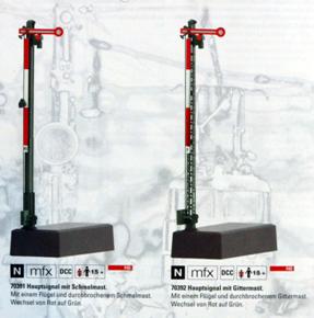
The following digital signals are not in
my possession, so I give links to the Märklin page: No. 70391 and 70392, Conditionally
conventionally controllable: exclusively with command panel 72760. No. 70393 and 70394, exclusively digitally controllable. |
|
|||||||||||||||||||||||||||||||||||
|
For a detailed description
of the Märklin command and switch panels see Two aspect
light main signals: |
||||||||||||||||||||||||||||||||||||
|
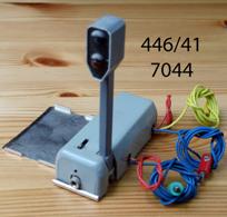
similar to a traffic
light, No. 446/41, No. 7044, |
|
|||||||||||||||||||||||||||||||||||
|
similar to a railway signal No. 7188, |
|
|||||||||||||||||||||||||||||||||||
|
Spare parts: Both signals are switched
conventionally with double solenoid actuator. Note: The white-red-white
"Mastschild" is missing. The following signals are
not in my possession, so I give links to the Märklin page: |
||||||||||||||||||||||||||||||||||||
|
No. 7239, prototypical, in the catalog from 1969
until 2003: Spare parts: Note: The white-red-white
"Mastschild" is missing. |
|
|||||||||||||||||||||||||||||||||||
|
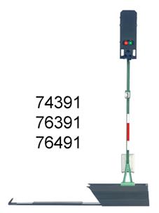
No. 74391,
No. 76391,
No. 76491,
Mounting on C- and K-track |
|
|||||||||||||||||||||||||||||||||||
|
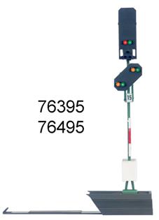
Combination of block and
distant signals No. 76395,
No. 76495,
Mounting on C- and
K-track. |
|
|||||||||||||||||||||||||||||||||||
|
For a detailed description
of the Märklin command and switch panels see We take
a closer look at the distant signal: A distant signal is usually
directly coupled to the following
main signal in the set route and
indicates its current position. Because of this direct
coupling, a combination of mechanically set semaphore signals and
electrically set light distant signals and vice versa rarely occurs. The distance to the main
signal is usually 700 m or 1000 m on main lanes on open routes due to the
regular braking distance, on secondary lanes it can also be only 400 m. (The
scaled conversion to the model railway layout is usually not possible.) |
||||||||||||||||||||||||||||||||||||
|
The distant signal to a
block signal is just like this two-aspect: |
|
|||||||||||||||||||||||||||||||||||
|
1st Aspect "Vr0" for "Expect
stop", represented by two yellow lights rising to the right, with the
semaphore distant signal additionally by a vertical round disc with an orange
area with a black border and a white border around it. 2nd Aspect "Vr1" for "Expect proseed", represented by two
green lights rising to the right, with the semaphore distant signal
additionally by the horizontal and thus invisible pane folded backwards. A distant signal is
identified as such by the distant signal board Ne2. Handicraft suggestion: On
branch lines, the distant signal can also be replaced by the distant signal
board alone. For epochs 3 and 4: If the
distance between the distant signal or the distant signal board and the
associated signal is more than 5% shorter than the braking distance in this
section of the route, the distant signal board has a white triangle with a
black border on its upper edge. Since the shorter distance is usually on model
railways and the Märklin distant signals do not have this triangle, this is a
useful addition. Märklin distance signals
for block signals: Two-aspect
semaphore distant signals for semaphore block signals: |
||||||||||||||||||||||||||||||||||||
|
No. 446/1, No. 7036, Conventional with double
solenoid actuator that moves the disc and the shades in front of the lights. Spare part: light bulb No.
60000 |
|
|||||||||||||||||||||||||||||||||||
|
The following digital
signals are not in my possession, so I give links to the Märklin page: No. 70361, No. 70362, |
|
|||||||||||||||||||||||||||||||||||
|
Two aspect light distant
signals for light block signals: The following signals are
not in my possession, so I give links to the Märklin page where available: |
||||||||||||||||||||||||||||||||||||
|
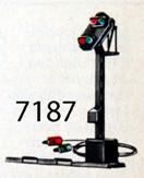
No. 7187, in the catalog
from 1959 until 1997. Base plate for M-track
included. Note: The distant signal
board Ne2 is missing! |
|
|||||||||||||||||||||||||||||||||||
|
No. 7236, in the catalog from 1969 until 2003, Note: The distant signal
board Ne2 is missing! Spare parts: |
|
|||||||||||||||||||||||||||||||||||
|
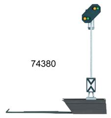
No. 74380, |
|
|||||||||||||||||||||||||||||||||||
|
Combination of block and
distant signal: No. 76395,
No. 76495,
Installation on C and K
track. |
|
|||||||||||||||||||||||||||||||||||
|
For a detailed description
of the Märklin command and switch panels see We
reach the next block signal, as expected it shows "proseed" =
"Hp1". It
is the last block signal before the train station. The main signal is
identical to the previous one. The
distant signal differs from the previous one: A third signal aspect can be
set: "Vr2". Why? Every train station begins with a turnout. (Note:
Without a turnout it is only a stop!) The "entry signal" is in front of this
first turnout. If the turnout is set straight ahead and all
following turnouts on the route through the station too, you can drive at the
highest speed for this section of the route, the "entry signal" of
the train station is - if nothing speaks against it - on "Proseed"
= "Hp1", the corresponding distant signal "Expect
proseed" = "Vr1". If the route leads over a deflecting turnout, it
may only be driven on at reduced speed due to the strain on the curved turnut
tongue, usually at 40 km/h, and the entry signal is set to "Proseed at
reduced speed" = "Hp2", the associated distant signal
analogously "Expect proseed at reduced speed" = "Vr2". If the train stations tracks are occupied, the
entry signal is set to "Stop" = "Hp0", the corresponding
distant signal correspondingly "Expect stop" = "Vr0". We
find the distant signal with "Vr2", because there is a stop in the
train station and we have to clear the continuous track for the faster train,
so we are directed to the siding by the deflecting turnout. The
overtaking train will find "Vr1" here and it will drive through the
continuous track at the maximum permissible speed. We take a closer look at the distant signal for
the entry signal: A distant signal is
directly linked to the following main signal in the set route and shows its
current position. Because of this direct
coupling, a combination of mechanically set form main signals and
electrically set light distant signals and vice versa rarely occurs. The distance to the main
signal is usually 700 m or 1000 m on main lanes on open routes, due to the
regular braking distance, on secondary lanes it can also be only 400 m. The distant signal to the entry signal has three aspects: The three aspect light
distant signal is externally identical to the two-aspect described above, it
is only switched differently.
"Vr0" as with
the two-aspect distant signal. The additional wing points straight down. "Vr1" as with
the two-aspect distant signal. The additional wing points straight down. "Vr2" = a yellow
light at the bottom left and a green light at the top right, with the
semaphore distant signal additionally the vertical round disc described
above. The additional wing points to the lower right. Before 1959 the form
distant signal showed two yellow lights rising to the right and a green light
under the upper yellow one. This night signal image is in the Signal Book
1959 under no longer applicable signals with an undefined transition period.
It can be assumed that distant signals of this type were/are still to be
found in later epochs. A distant signal is
identified as such by the distant signal board Ne2. In the case of the
three-point distant signal, a triangular, black-rimmed, white board with a black
point can be attached above the distant signal to identify this property. Here, too, the same
handicraft suggestion as for the distant signal to the block signal, the
board for shortened braking distance. Märklin distant signals
for the entry signal: Three-aspect semaphore
distant signals for entry signals: |
||||||||||||||||||||||||||||||||||||
|
No. 446/3, No. 7038, Night signal from before
1959, Spare part: light bulb No.
60000 |
|
|||||||||||||||||||||||||||||||||||
|
The following digital signals
are not in my possession, so I give links to the Märklin page: |
||||||||||||||||||||||||||||||||||||
|
No. 70381, No. 70382, Note: |
|
|||||||||||||||||||||||||||||||||||
|
Three-aspect light distant
signals for light entry signals: The following signals are
not in my possession, so I give links to the Märklin page: |
||||||||||||||||||||||||||||||||||||
|
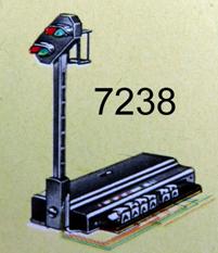
No. 7238, Spare parts: light bulb Note: The distant signal
board Ne2 is missing! |
|
|||||||||||||||||||||||||||||||||||
|
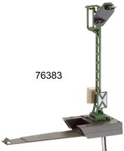
No. 76383, Note: The triangular
supplementary sign to identify the three-aspect distant signal is missing on
the Ne2 signal board. |
|
|||||||||||||||||||||||||||||||||||
|
No. 76480 and no. 76481, Conditionally
conventionally controllable: exclusively with command panel 72760. Note: The triangular
supplementary sign to identify the three-aspect distant signal is missing on
the Ne2 signal board. |
|
|||||||||||||||||||||||||||||||||||
|
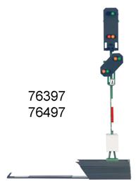
Combination of main and
distant signal No. 76397,
Conventionally
controllable with command panel 72720/72729 or predecessor. No. 76497,
Conditionally
conventionally controllable: exclusively with command panel 72760. Installation on C and K
track. |
|
|||||||||||||||||||||||||||||||||||
|
For a detailed description
of the Märklin command and switch panels see We
passed the last block signal, it dropped to "Stop" behind us, and
the train reduced its speed with the aim of only driving 40 km/h at the entry
signal. The
entry signal comes into view, it shows "Proceed at reduced speed" =
"Hp2", as expected. The
distant signal at the same place shows "Expect stop" =
"Vr0", the train will stop at the train station. This
distant signal has three aspects because it is assigned to different exit
signals depending on the route. All
three terms are possible depending on the exit situation: 1st
"Expect stop" = "Vr0", if the
incoming train has to stop, regardless of the track. 2nd
"Expect proceed" = "Vr1", if the
arriving train drives through and is not directed over dis-tracting turnouts
when leaving. 3rd
"Expect proceed at reduced speed" =
"Vr2", when the incoming train drives through and is directed over
distracting turnouts when leaving, the exit signal is on "Hp2". We
slowly drive over the deflecting turnout into the train station ... |
||||||||||||||||||||||||||||||||||||
|
We already know: A main
signal is identified by the white-red-white mast sign or the mast plate, see
"We take a closer look at the
German block (main) signal". With this main signal,
three signal positions are possible, it is "three-aspect". |
|
|||||||||||||||||||||||||||||||||||
|
The main semaphore signal
has a second wing below the main wing. The main light signal has
another yellow light at the bottom right, the green
light is placed here at the top of the signal screen. The signal terms are: 1st "Stop" = "Hp0", one red
light, with the semaphore main signal the upper wing is horizontal, the lower
wing is vertical in front of the mast. 2nd "Proceed" = "Hp1", one
green light, with the semaphore main signal the upper wing is upwards, the
lower wing is vertical in front of the mast. 3rd "Proceed at reduced speed" =
"Hp2", one green light above and one yellow light below, with the
main semaphore signal both wings point upwards. A light distant signal at
the same location as a main light signal is switched off at Hp0! Märklin entry signals: Three-aspect semaphore
main signals: |
||||||||||||||||||||||||||||||||||||
|
No. 446/13, No. 7041, Convetional with triple solenoid
actuator, Spare parts: lightbulbs
No. 60000 |
|
|||||||||||||||||||||||||||||||||||
|
The following signals are
not in my possession, so I give links to the Märklin page: |
||||||||||||||||||||||||||||||||||||
|
No. 70411 and no. 70412, No. 70413 and no. 70414, |
|
|||||||||||||||||||||||||||||||||||
|
Main light signals with
three aspects: The following signals are not
in my possession, so I give links to the Märklin page: |
||||||||||||||||||||||||||||||||||||
|
No. 7241, Note: The white-red-white
"Mastschild" is missing. Spare parts: |
|
|||||||||||||||||||||||||||||||||||
|
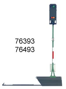
No. 76393,
No. 76493,
Installation on C and K
track. |
|
|||||||||||||||||||||||||||||||||||
|
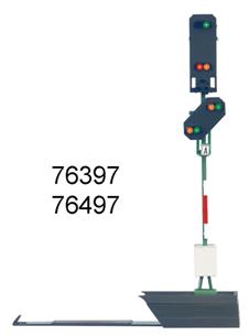
Combination of main and
distant signal, No. 76397,
No. 76497,
Installation on C and K
track. |
|
|||||||||||||||||||||||||||||||||||
|
We
stopped in front of the "exit signal" in the train station because
it shows "Stop" = "Hp0". The
entry signal behind us changed to "Stop" = "Hp0" after we
drove past, then the turnout was set to straight ahead, of course the
turnouts at the exit of the train station, then the entry signal was set to
"Proceed" = "Hp1" for the following fast train. Our
stop in the train station can be a scheduled stop, travelers get on and off,
or an unscheduled stop, in which case the doors usually remain closed. We look at the exit (main) signal in front of us. We already know: A main
signal is identified by the white-red-white mast sign or the mast plate, see
"We take a closer look at the
German block (main) signal". This exit signal initially
looks exactly like the entry signal. The invisible difference is that THIS
signal does not need to be able to use the term "Proceed" =
"Hp1". The route from this siding
always leads over a distracting turnout, therefore
the exit signal HERE only needs to be able to show "Hp0" and
"Hp2". The wings of the semaphore signal are coupled and always
move together. The signal aspects are: 1st "Stop" = "Hp0", one red light, with the semaphore signal
the upper wing is horizontal, the lower one vertically in front of the mast. 2nd "Proceed at reduced speed" =
"Hp2", one green light above and one yellow light below, with the
semaphore signal both wings point upwards. A light distant signal at
the same location as a main light signal is switched off at Hp0! Märklin exit signals for
sidings, etc.: Two-aspect semaphore main
signals with coupled wings: |
||||||||||||||||||||||||||||||||||||
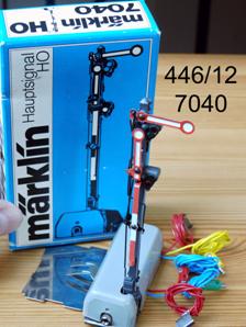
|
No. 446/12, No. 7040, Conventional with double
solenoid actuator, Spare parts: lightbulbs
No. 60000 |
|
|||||||||||||||||||||||||||||||||||
|
The following signals are
not in my possession, so I give links to the Märklin page: |
||||||||||||||||||||||||||||||||||||
|
In the catalog from 2013
until today no special version, because no. 70411 and no. 70412 as well no. 70413 and no. 70414 can represent the aspects. See above. |
|
|||||||||||||||||||||||||||||||||||
|
Two aspect light main
signals for exit signals: The following signals are
not in my possession, so I give links to the Märklin page: |
||||||||||||||||||||||||||||||||||||
|
No. 7240, Note: The white-red-white
"Mastschild" is missing. Spare parts: |
|
|||||||||||||||||||||||||||||||||||
|
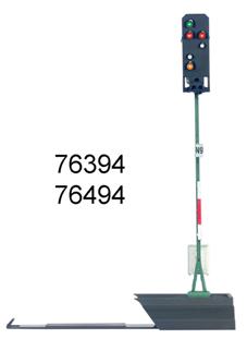
Exit main signal with
integrated yard signal No. 76394,
No. 76494,
Installation on C and K
track. |
|
|||||||||||||||||||||||||||||||||||
|
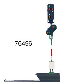
Combination of main and
distant signal, No. 76496, Installation on C and K
track. |
|
|||||||||||||||||||||||||||||||||||
|
We consider the exit
signal on the adjacent continuous line track: In the case of a continuous
track, there is usually no distracting turnout that would hinder the passage.
Therefore, the exit signal can be identical to a block signal. Otherwise,
signal aspects corresponding to the route guidance are required. Some exit signals from a
train station are often combined with another signal, the yard signal. With
the semaphore main signal, this is before the exit signal, with the light
main signal it is integrated: ... is
a protection signal. The Deutsche Bahn signal book
defines: "Protection signals
are used to close off a track, to give the order to stop or to indicate the
lifting of a driving ban." Märklin has only one
protection signal, the yard signal. Yard signals apply to
shunting trips and are available wherever shunting trips and shunting trips
with train trips can overlap, namely in front of turnouts. They allow and
forbid shunting movements, controlled by the turnout attendant. In the passenger station
track, shunting trips can be e.g. the change of locomotive and the provision
or withdrawal of express and post coaches or the formation of trains.
Therefore, a yard signal against the direction of travel often belongs in
front of the turnout at the beginning of the track. For this there are
stand-alone yard signals as semaphore and light signals. They can usually be found
on all turnouts in the freight yard. Read more:
https://en.wikipedia.org/wiki/German_railway_signalling#Schutzsignale We take a closer look at
the yard signal: |
||||||||||||||||||||||||||||||||||||
|
The SEMAPHORE yard signal
consists of a square box on a mast. |
|
|||||||||||||||||||||||||||||||||||
|
It is rare to find
semaphore yard signals in dwarf form, with an arrangement close to the ground
(handicraft idea), if the high version would protrude into the clearance
profile. The LIGHT yard signal is
either integrated into the signal screen of an exit signal or it is designed
as a stand-alone rectangular box with beveled upper corners on a mast or in
an arrangement close to the ground if the high version would protrude into
the clearance profile. A light yard signal can
carry a "Mastschild" like a light main signal. The protection signal has
two aspects: 1st "Stop! Proceed ban"=" Sh0 ": 2nd "Proceed ban lifted" = "Sh1": If a SEMAPHORE yard signal
precedes a SEMAPHORE exit signal, it must be set to "Sh1" at
"Hp1" or "Hp2". Yard signals by Märklin: Semaphore yard signals: |
||||||||||||||||||||||||||||||||||||
|
No. 446/21, No. 7042, Conventional with double
solenoid actuator, Spare part: light bulb No.
60000 |
|
|||||||||||||||||||||||||||||||||||
|
The following signals are not
in my possession, so I give links to the Märklin page: |
||||||||||||||||||||||||||||||||||||
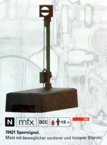
|
No. 70421, No. 70422, |
|
|||||||||||||||||||||||||||||||||||
|
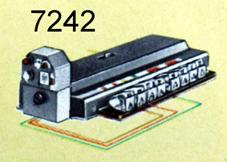
Stand-alone light yard
signals: |
||||||||||||||||||||||||||||||||||||
|
No. 7242, Spare part: |
|
|||||||||||||||||||||||||||||||||||
|
No. 74371,
No. 76371 and no. 76372, No. 76471 and no. 76472, Installation on C and K
track. |
|
|||||||||||||||||||||||||||||||||||
|
|
||||||||||||||||||||||||||||||||||||
|
Märklin light exit signals
are available in the variant with distant signal: This only makes sense if
the next main signal is 1000m or less away. Otherwise it is cheaper (installation,
maintenance) to set up a single distant signal after the end of the station
instead on every station track. A light distant signal at
the same location as a main light signal is switched off at Hp0! |
|
|||||||||||||||||||||||||||||||||||
|
The next signal after the
exit signal is usually a block signal, so two aspects on the distant signal
are sufficient. If there is a crossing point or a level junction, the distant
signal needs 3 aspects; see below. The
faster train has passed, the exit signal on the
continuous track now shows "Hp0". The
turnout in front of us is set so that we can drive on it. Since
the route is now set correctly, our journey could continue. However,
the other train is still in the block in front of us, so we have to wait. After
the other train has completely passed the next block signal, our exit signal
goes to "Hp2" = "Proceed at reduced speed" and the yard
signal to "Sh1" = "Proceed ban lifted". The
train now travels with max. 40 km/h out of the station on the free route. The
train driver knows how long his train is and accelerates when the last car
has left the last turnout. The
next distant signal announces "Expect to proceed" = "Vr1"
because the other train has already left the next block. A danger point is
protected with a cover signal. A cover signal can also be a block signal at
the same time. A cover signal, regardless
of the design, is announced by a distant signal. On our journey we
repeatedly come across transition points where a train can be directed to the
opposite track and/or back from the opposite track. These transition points
are needed if the direction track is blocked due to an accident or a
construction site. There is a main signal in
front of the first switch, a cover signal, which can also be a block signal.
If a deflecting turnout follows, this main signal has three aspects Hp0/Hp1/Hp2, otherwise it has two aspects Hp0/Hp1. If the line is equipped with
light signals, bidirectional running is possible
(https://en.wikipedia.org/wiki/Double-track_railway#Bi-directional_running ). At a level junction, a
branching railway line joins the trunk line. Main signals, cover signals,
which can also be block signals, are in front of the turnout(s) from all
three directions. If there is a possible
distracting route, there is a three-aspect main signal, and a two-aspect
signal from the direction that only leads straight ahead. There is a two-aspect main
signal Hp0/Hp2 from the direction of the junction at the merging track,
because the route always goes over a deflecting switch. The distant signal is
also two-aspect: Vr0 and Vr2! We take a closer look at the distant signal at the
merging track A distant signal is
directly linked to the following main signal in the set route and shows its
current position. Because of this direct
coupling, a combination of mechanically set semaphore signals and
electrically set light signals rarely occurs. The distance to the main
signal is usually 700m or 1000m on main lanes on the open road due to the
regular braking distance, on secondary lanes it can also be only 400m. The distant signal to the
main signal in the direction of a junction has only two aspects, because a
deflecting turnout is used: |
||||||||||||||||||||||||||||||||||||
|
1st "Vr0" for "expect stop"
and 2nd "Vr2" for "expect proceed at reduced speed". The
semaphore signal has a rotating wing for this purpose. |
|
|||||||||||||||||||||||||||||||||||
|
The light distant signal is
externally identical to the two-aspect described above, it is only switched
differently. "Vr0" as with
the two- and three-aspect distant signals. The additional wing points
straight down. "Vr2" = one yellow
light at the bottom left and one green light at the top right, with the
semaphore distant signal the round disc is fixed vertically and the
additional wing points to the bottom right. Before 1959, the semaphore
distant signal showed two yellow lights rising to the right and one green
light under the upper yellow one. I mentioned it above. A distant signal is
identified as such by the distant signal board Ne2. Here, too, the same
crafting suggestion as for the distant signal for the block signal. Märklin distant signals
for the main signal Hp0/Hp2: Two-aspect semaphore distant signal Vr0/Vr2: |
||||||||||||||||||||||||||||||||||||
|
No. 446/2, No. 7037, Conventional with double
solenoid actuator for the additional arrow, the round disc is fixed. Base plate for M-track. Spare part: light bulb No.
60000 This signal was probably
no longer offered after 1975 due to the low demand. The three-aspect
semaphore distant signal No. 7038 can represent the aspects. |
|
|||||||||||||||||||||||||||||||||||
|
In the catalog from 2013
until today, no specific variant is offered within the scope of the new semaphore
signals, because the three-aspect semaphore distant signal No. 70381
described above can represent the aspects. In 2018, the purely digital
version No. 70382 was added. Two-aspect light distant signal Vr0/Vr2: |
||||||||||||||||||||||||||||||||||||
|
No. 7237, Spare parts: light bulb Note: The distant signal
board Ne2 is missing. As of 2004, no specific light
distant signal was offered any more, because the three-aspect light distant
signals described above no. 76383 and 76483 can represent the aspects. |
|
|||||||||||||||||||||||||||||||||||
|
Exotic signals from the Märklin range Main light signal with manual activation on the signal. The two-aspect light
signal is permanently mounted on a straight section of track half the length.
It is operated via a slide switch on the signal base. The train control is permanently
installed; For this purpose, half a straight piece of track with a central
conductor interruption is part of the set (the electrical connection is
explained below).
source:
German Märklin catalog 1976 With M-track: With K-track: Note: The white-red-white
"Mastschilder" are missing. Spare parts: light bulbs For the sake of
completeness: On "hump" of a
German marshalling yard / classification yard there is often a semaphore fly shunting signal or its successor as a light
signal. The semaphore fly shunting
signal has three aspects: 1st "Ra6" = "Stop! No shunting", a horizontal white bar with
a black border 2nd "Ra7" = "Shunt slowly",
a white bar with a black border diagonally upwards to the right 3rd "Ra8" = "Shunt fairly
fast", a vertical white bar with a black border (The fly shunting light signal can also show
"Ra9" = "Withdraw".) The fly shunting signal from Märklin
for M-track: |
||||||||||||||||||||||||||||||||||||
|
No. 446/22, No. 7043, Conventioal with triple
solenoid actuator, A rare signal on the used market,
therefore correspondingly expensive. In the late 1950s, hardly
anyone had the space for a marshalling yard the size that a fly shunting hill
made sense, so sales were probably low. |
|
|||||||||||||||||||||||||||||||||||
|
Without a real prototype: |
||||||||||||||||||||||||||||||||||||
|
... indicates
when the uncoupling track is operated. No. 3601 EKL, No. 5113, No. 74997, Spare part: light bulb No.
60010 |
|
|||||||||||||||||||||||||||||||||||
|
The installation of conventional Märklin H0
signals on the conventional layout Since I only own conventional
signals, i.e. only those with double or triple solenoid actuator and
four-digit number, I will only describe the installation for these. First, let's look at the
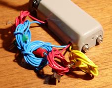
routing of the connection lines. The signals of the series
446/xx, 70xx and 71xx have the following connection cables: o
2x red with
connection shoes for M-track center conductor (not with the distant signals
and not with the 72xx series) o
1x yellow with
yellow plug o
2x blue with red and
green plugs Since the connection to
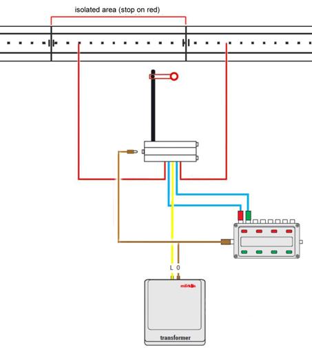
the track should be done first, let's first consider ... The main signals, the yard
signals and the fly shunting signal (not the distant signals) have two switch
contacts for so-called "train control". The train control system
directs the voltage to an isolated zone in front of the signal if the signal
permits the journey. The isolated zone is
created by two interruptions in the center conductor and in the catenary, one
directly in front of the signal, the other so far in front of the signal that
no locomotive can slide past the signal without power. (The train driver must
still be able to see the signal when the locomotive has come to a
standstill.) This is what Märklin
originally thought. The train travels from an
area with high voltage to a zone with no voltage; it therefore stops
relatively abruptly.
How do you make the isolated zone? When plugging the tracks
together, insulating material is attached between the plug contacts of the
center conductor. With the M track, cardboard, paper or plastic film
is placed between the central conductor tongues. Märklin delivered finished
cardboard strips under the no. 5022.
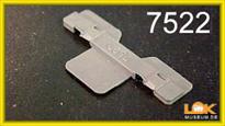
For the K track there is the "middle
conductor insulation" in a pack of 5 under no. 7522. It is also possible with
paper, but quite fiddly.
With the C track you have to put a red insulating
cap on each side of the rail joint; these are available as "center
conductor insulation" under no. 74030 in a pack of 8, ie for 4
insulation points. Here, too, you can make it
with insulating materials, but it is very fiddly.
The creation of an
isolated zone in the catenary is described in their instructions. Where do
you connect the red wires? The signals of the 446/xx,
70xx, 71xx and 72xx series have tin shoes soldered
to the ends of the red lines. In the case of the M track, the tin shoes are pushed between
the center contact lugs of a track joint: one shoe inside the isolated zone,
the other outside the isolated zone. Spare part: tin shoe with
cable and plug no. 5004
In the case of the K track, the tin shoes are unsoldered /
cut off and the cables are each clamped to a center conductor connection no.
7504. One connection is made inside the isolated zone, the other outside.
In the case of the C track, the tin shoes are unsoldered /
cut off and replaced by 3mm cable lugs. One line is connected inside the
isolated zone in the track, the other outside. The drawing also shows the
brown "0" connection, which we will talk about below.
... supplies
the solenoids of the actuators and the signal lamps with 16V and therefore
belongs to the "L" connection of the transformer. It makes sense to lay a
ring line with a wire size of 1 to 1.5 mm² from this transformer connection
around the entire system, because this power source is needed everywhere. If the number of turnouts,
signals and building lights increases, it makes sense not to burden the
driving transformer with this, but to use a separate light transformer, e.g.
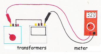
B. no. 6611 or no. 6002. ATTENTION,
safety-relevant notice: All transformers in the
system must be connected in phase! To do this, all
transformers are connected to a common connector strip with a switch. The "0" connections
of the transformers must be connected. The phase equality is
checked by measuring the voltage between the yellow connections of two
trans-formers:
o
at or near 0V the
alignment of the power plugs is OK, o
at 32V, FIRST switch off the power strip AND THEN turn the power plug of one of
the transformers. If you do not switch off
the power strip, a high voltage may be present on the unplugged plug! See
also my page "Driving
with several transformers - Danger from incorrect connection": If there are more than 2
transformers, this test must be carried out with all transformers, always
measuring between the newly added one and one that has already been tested. If 0V is applied
everywhere, you leave the power plug in the power strip "for all
times" and always switch the power supply on and off using the switch on
the power strip. A circuit always has two
connections. For the signal lamps, the
second is the "0" connection of the transformer. |
||||||||||||||||||||||||||||||||||||
|
If you use the supplied
base plate on the M-track for the signals of the series 446/xx, 70xx, 71xx and
72xx, then you make this connection via the track body of the M-track,
because it is connected to the brown connection line at "0" -
Connection connected. |
|
|||||||||||||||||||||||||||||||||||
|
Since the catalog year 1982,
the tabs on the underside of the bedding have been completely folded in. This
increased the clearance and the base plates no longer jammed. This means that
you take an older section of track at this point. |
|
|||||||||||||||||||||||||||||||||||
|
Or you use the right-hand
variant of the base plate, the newer variant that came about because of the
change to the M track described above. This variant can also be used on C
track. |
|
|||||||||||||||||||||||||||||||||||
|
If you set the signal alone
without contact to the track, then a brown wire must be laid to the
"0" connection of the transformer. If you lead this 0-line over
a switch, you can turn off the signal lamps. For example, with semaphore
signals during the day. It makes sense to lay a
ring line with a wire size of 1 to 1.5 mm² from this "0" connection
of the transformer around the entire system, because this connection is
needed everywhere. As I said: A circuit
always has two connections. For a
actuator solenoid, this is also the "0" connection of the
transformer, but - important -
only for a short moment, a "momentary
contact". Each of the solenoids in
the actuator of the signals and turnouts has a blue connection cable, if
complete, with a red, green or orange plug. If you want to set a
signal or a turnout by hand, you can use the blue Märklin momentary contact command
panels or two standard push buttons (momentary contact, normal open
contact). Connect the blue lines to
the momentary contact command panel at the back according to the connector
colors or vice versa. You can follow the Märklin
philosophy or your own. Try it! So that the signal moves
and the circuit is complete, a brown wire must be led from the side of the
command panel to the "0" connection of the transformer.
The blue line with the
orange connector occupies a second pair of buttons. You can operate several
signals and / or turnouts with the same button, which saves hand movements. How are the signals actuated, how do they work? Actuator and function of the signals for M-Track, series 446/xx and
70xx and 71xx |
||||||||||||||||||||||||||||||||||||
|
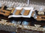
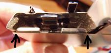
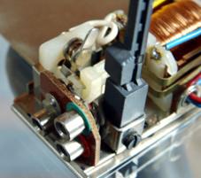
Under the gray covers that
can be seen on most of the pictures in this description there are two
solenoids that pull a rectangular iron core back and forth. The power of this
electromagnetic actuator is strong enough to move the blades and discs with
the semaphore signals via levers and rods. On the extension of this
"magnet armature" there are 2 contact surfaces made of copper,
which are touched or not by contact springs during this back and forth
movement. For all main signals and
for the yard signal, these contacts are closed in the "Proceed"
position and open in the "Stop" position. |
|
|||||||||||||||||||||||||||||||||||
|
These contacts are the
"train control" for the central conductor and the catenary, which
causes the train to stop or drive past the signal. The two red lines are
connected to one contact with the metal tabs. The double solenoid
actuator is bistable, means it maintains its position in the event of a power
failure. |
||||||||||||||||||||||||||||||||||||
|
With light signals no. 7044
and no. 7188, the switch for the light change is operated like the linkage of
the semaphore signals. This switch has a hand lever that protrudes from the
top of the housing. |
|
|||||||||||||||||||||||||||||||||||
|
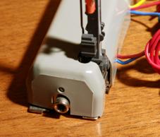
At the end of the actuator
facing away from the signal mast there is the pair of sockets, which are
connected to the second pair of contacts on the magnet armature for
influencing the electricity of the catenary: "Proceed" position
connected, "Stop" position separate. |
|
|||||||||||||||||||||||||||||||||||
|
A few additional
applications for this are described in the subject area "Circuits for
advanced users - automation of processes". The solenoids and the
signal lamps are supplied with the yellow cable from the "L" connection
of the transformer. The second connection for
each solenoid, the "0" connection for the "Stop" position
is made via the blue cable with the red plug, the "0" connection
for the solenoid for the "Proceed" position is made via the blue cable
with the green plug. |
||||||||||||||||||||||||||||||||||||
|
The three-aspect main
signal No. 7041 and the fly shunting signal No. 7043 have a third solenoid
with which the third aspect is switched. The third solenoid is connected to
the "0" connection via a third blue cable with an orange plug. |
|
|||||||||||||||||||||||||||||||||||
|
With the main signal no.
7041, the third solenoid moves the lower wing and the upper wing at the same time
into the inclined position. In thr picture you can see the adjusting rod. The
return to the "Stop" position of both wings causes the solenoid for
the "Stop" position. The solenoid actuator
retains its position in the event of a power failure. |
||||||||||||||||||||||||||||||||||||
|
With the fly shunting
signal no. 7043 the third solenoid swivels the signal bar from the horizontal
to the inclined position, thus moving the magnet armature halfway. |
|
|||||||||||||||||||||||||||||||||||
|
The solenoid for
"Shunt fairly fast" turns the bar in the vertical position, ie up
to the stop, the solenoid for "Stop! No shunting" into the
horizontal position, up to the other stop. IMPORTANT: This connection
to "0" may only be made for a short time, i.e. via a button or a
contact or switching track, because the solenoids are not designed for
continuous operation and can burn out. |
||||||||||||||||||||||||||||||||||||
|
The transformer connection
at "0" for the signal lamp(s) is connected via the base plate or
the individual socket near the mast. The fly shunting signal
has no lamp. |
|
|||||||||||||||||||||||||||||||||||
|
The two-aspect (Vr0/Vr1) semaphore
distant signal No. 7036 has a double solenoid, just like the two-aspect
(Vr0/Vr2) semaphore distant signal no. 7037. The double solenoid
actuator is bistable, means it maintains its position in the event of a power
failure. |
||||||||||||||||||||||||||||||||||||
|
The three-aspect semaphore
distant signal No. 7038 has a second pair of solenoids for the third term. The second solenoid only
moves the auxiliary wing in both directions. |
|
|||||||||||||||||||||||||||||||||||
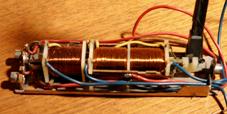
|
The semaphore distant
signals and the semaphore yard signal have a mirror image arrangement of the
actuator as the main signals so that the masts can be placed as close as
possible to one another. |
|
|||||||||||||||||||||||||||||||||||
|
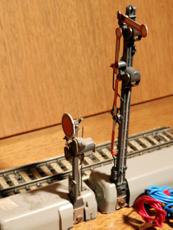
In the description of the
exit signal, I mentioned that it might not make sense to put distant signals
in front of every exit signal at a train station, but rather one behind the
train station. If there is a yard signal
in front of the exit signal, there is no longer any space for a distant
signal. The distant signal no.
7187 has no foot housing, because it has no mechanics. The narrow base plate
works in the same way with the M-rails. It is connected to the
colored sockets on the main light signal no. 7188, on the mast-side face of
the housing next to the "0" connection socket. |
||||||||||||||||||||||||||||||||||||
|
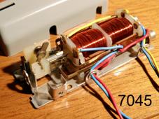
If you take away the mast of
the main light signal No. 7044, you almost have the universal remote control
switch No. 7045. In addition to the missing
signal mast, there is also no "0" connection socket on the front
wall of the housing and - when the housing is opened - the electrical
function of the hand lever is missing. |
|
|||||||||||||||||||||||||||||||||||
|
The universal remote
control switch is actuated by a signal double solenoid. As a result, the
universal remote control switch is bistable and retains its switch position when
the voltage drops out. The contacts on the
armature are different to those of the signals. The universal remote control
switch has only one contact set, one changeover switch. The red lead is
alternately connected to one of the two sockets at the end of the housing. The yellow lead with the
yellow plug supplies the coils from the "L" connection of the
transformer. The blue lines with the
red and green plugs give the "0" connection to one solenoid each.
This way the universal remote control switch is switched. IMPORTANT: This
transformer connection to "0" may only be made for a short time,
i.e. via a button or a contact or switching track, because the solenoids are
not designed for continuous operation and can burn out. In the catalog from 1955
until 1975: No. 7045 Actuator and function of the signals for K and M track, series 72xx The K-track and the light
signals of the 72xx series appeared for the first time in the 1969 catalog. |
||||||||||||||||||||||||||||||||||||
|
These light signals also have
a double solenoid actuator, but in a much slimmer design. I don't have any of the
72xx signals, but a universal remote control switch No. 7245 of this
generation. |
|
|||||||||||||||||||||||||||||||||||
|
The actuators of the 72xx
light signals are similar to these. We see a yellow lead with
a yellow plug for connection to the "L" socket / terminal of the
transformer. The switchover takes place
through alternating contact of the blue lines with the red and green plug
contact on the "0" connection of the transformer. IMPORTANT: This connection
to "0" may only be made for a short time, i.e. via a button or a
contact or switching track, because the solenoids are not designed for
continuous operation and can burn out. This unit has a changeover
switch and two normally open / normally closed contacts. The power supply for the
red and green lamps is connected to the signal on the changeover switch. The 7236
distant signal, which, as is well known, does not have its own switching
element, can be connected to the associated terminals. The lamps get the
"0" connection via the metal mast. One of the NC/NO contacts
is used as "train control" on the center conductor, the other is
for the catenary - just like with the signals of the 70xx and 71xx series.
"Proceed" position connected,
"Stop" position disconnected. A few additional applications for the
catenary contact are described in the subject area "Circuits for
advanced users - automation of processes". The base plates were now,
in 1969, available under a separate number, also in a special version for the
K track. So you could combine the signals with M and K tracks as desired. The M-base plates were
included with the 70xx and 71xx signals. For the 72xx you had to buy the
required extra. The distant signal 7236
does not have a base plate, but a base bracket to screw on, because this
signal has no mechanics and therefore no housing on the base. In the 1973 catalog, the
base plates for the M track were no longer listed separately and, according
to the description, were still included with the 70xx and 71xx signals. The
base plates for the K-tracks still had to be bought. In 1975 the K-base
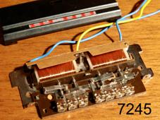
plates were included in the scope of delivery of the 72xx signals. The Universal remote control switch No. 7245,
later called Universal relay The universal remote
control switch No. 7245 shown in the above picture is actuated by a double
solenoid. As a result, the universal remote control switch is bistable and
retains its switch position when the voltage drops out. The armature moves a slide
to which 4 pins are attached that move 4 contact tongues. A changeover switch and
two NC/NO contacts are operated with it. The solenoids are
connected to the "L" connection via the yellow cable with the
yellow plug. Switching takes place by
alternately contacting the two blue lines with the red and green plugs with
the "0" connection. IMPORTANT: This connection
to "0" may only be made for a short time, i.e. via a button or a
contact or switching track, because the solenoids are not designed for
continuous operation and can burn out. The lines to be switched
are connected to the terminals. In the catalog from 1969
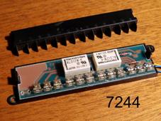
until 1999: No. 7245 The Universal remote control switch No. 7244,
later called Universal relay |
||||||||||||||||||||||||||||||||||||
|
The current universal
remote control switch No. 7244 now only contains two relays, a resistor and two
diodes, nothing moves visibly. You can hear a soft click when switching. The yellow supply line is
connected to the "L" connection, the two blue lines to switch
alternately to the "0" connection. |
|
|||||||||||||||||||||||||||||||||||
|
With this universal remote
control switch it is no longer important that the "0" connection of
the blue lines is only made for a short time. It does not hurt, therefore, if
e. g. the locomotive stops on the contact track. The universal remote
control switch is bistable, it retains its switch
position when the power supply is lost. This unit contains and
operates 4 changeover switches, the connections of which are externally
accessible via terminals. In the catalog from 1994
until today: No. 7244 Actuator and function of the signals for C-Track, series 70xxx, 74xxx
and 76xxx (5-digit numbers) Signals of the 70xxx,
74xxx and 76xxx series are built for digital operation and not all can be
operated in conventional mode. Light signals of the 74xxx
and 76xxx series (from 2004/2013) have bases for the C track and the K track
in the scope of delivery. Semaphore signals of the
70xxx series (from 2013) have large foot housings in which the servo actuator
is accommodated. This means that these signals can only stand alone. Information about the
inner workings of the signals is not available to me. Further media (without
guarantee) Today's German signaling rules
(German) The German signal books in the
original text (German) Facebook group "Signaltechnik"
(you have to answer difficult technical questions in German to access) Facebook group "Modellbahn:
Signal- und Stellwerkstechnik, Bahnhofsanlagen" Notes
on the graphic representation of German railway construction Books:
|
||||||||||||||||||||||||||||||||||||
|
|
|
|||||||||||||||||||||||||||||||||||
|
Further
links and German books: Ask me! |
||||||||||||||||||||||||||||||||||||
|
The Prototype Märklin-H0-Knowledge Layout-Building Modelstock |
||||||||||||||||||||||||||||||||||||
|
state: 21.11.2023 12:00 |
||||||||||||||||||||||||||||||||||||
|
Contact:
Mail |
||||||||||||||||||||||||||||||||||||