|
|
||||||||||
|
Contact: Mail |
||||||||||
|
Circuits for
advanced users – Automation of Processes My view concerning the term
“ANALOG” |
||||||||||
|
state: 22.07.2026 19:06 |
||||||||||
|
Translated from German by
Axel Wurl, later extended by Herbert Otto The reason for establishing my
exclusively German-speaking Facebook
group was the constant attempts by digital railroaders in
other groups to proselytize us conventional (analog) operators: “digitally,
everything is possible …” The thought, the idea, the feeling
that whatever would be possible digitally should actually also be feasible by
conventional means then gave me another reason to bring that community into
being. It soon showed, though, that a
multitude of members would rather need help with the basics than aim at
automated operation. This prompted the development of the series of articles
in the section “The very first basic knowledge about conventional controlled Märklin H0
model railways”. The idea to carry automation by
electromechanical means to extremes, step by step, and to illustrate the
possibilities as clearly and elaborately as possible has been my aim ever
since and is being covered in the section “Circuits for advanced users – automation of operations”.
There have been differences of
opinion about what kinds of operation aids may be discussed in my group. I am
describing and justifying the limits of tolerance within my group and this –
my – site in the treatise. Märklin HO ... : Every product that can be used
within the Märklin H0 system is of interest to us, thus, ·
all track systems with central rail conductors, rods
or studs, and generally or predominantly equal potential on both rails, even
if not produced by Märklin (e. g. home-made tracks), ·
all traction vehicles with a central pick-up shoe of
all manufacturers, including (home-made) conversions, made for, or adjustable
to, or automatically adjusting to control by alternating current (AC) of
varying voltage (so digital vehicles included), ·
all H0-scale railroad wagons of all manufacturers
(including conversions and home-made models) ·
all kinds of 1:87-scale model accessories ... analog control and
operation (from my group’s name) And here the problems begin... When what is commonly understood
by digital control of model trains first appeared on the market, “analog” was
chosen as a simple synonym for “not digital”, usually ignoring the fact,
though, that between black and white, digital and analog, there are countless
shades of gray. Digital, in the sense, refers to model railroad products
that communicate by means of encoded control signals sent simultaneously to a
multitude of ready-to-receive devices as an encoded pulse sequence through a
two-core wire, and the device addressed by this encoded control signal
decodes it and then performs the respective command. Analog, accordingly, refers to control signals, or better: control voltages,
sent directly from the control unit, through a multitude of wires, to each
individual device, without encoding and the necessary hard- and software. The differences of opinion I
mentioned before are fueled by the conventional (analog?) appliances, and
especially by the combination of such on a larger scale, and the use of
electronic aids. I will come back to this later on. The supposedly
knowledgeable model train enthusiast may find this trivial, but in case of
disputes, I will refer to the definitions in this treatise. In order for a
clear picture to evolve, it is necessary for me to split hairs. The definition of “analog”: Some synonyms for analog are: · continuous, constant, stepless. The definition of “analog
signal”: ·
a signal with a stepless and uninterrupted
behavior. An example of truly analog devices supposedly
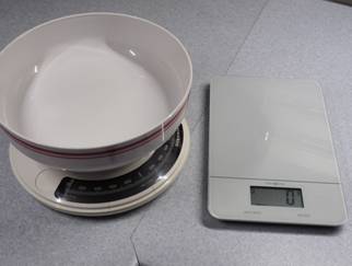
everybody knows: The kitchen or bathroom scale. Both mechanical and
electronic versions are available. |
||||||||||
|
The mechanical
scales (left) are analog. A spring is tensioned by the
weight force applied, and a hand displays the deflection on a scale with a
pointer - continuously, steadily, stepless! |
|
|||||||||
|
Some electronic scales
(right) are controlled digitally. They measure the weight by means
of electronic sensors at regular intervals and show the values at these
intervals, rounded, on a digital display. Scales which such behavior do NOT
work continuously, NOR steadily, NOR stepless. |
||||||||||
|
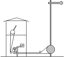
Semaphores, with their arms moved
by means of wire ropes, are also arguably analog. The signal arms move as the
signalman determines by hand. |
|
|||||||||
|
What do you see before your mind’s eye when you think
of an conventional, “analog” model train? |
||||||||||
|
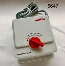
1st: A transformer, and
often a number of them. (Transformer here signifies a
control device with a turning knob or handle that allows adjustment of the
output voltage.) |
© Herbert Otto |
|||||||||
|
Heretic question: Is a Märklin transformer
really “analog”? Continuous, steady, stepless? My answer is NO! Slowly turning the knob or handle
to the right, at first, nothing happens. With a measuring device (voltage
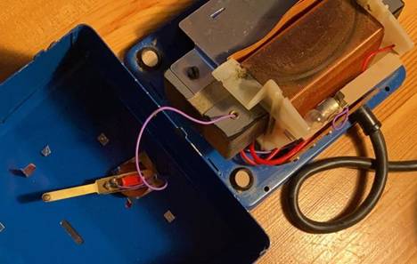
meter), we will see that the output voltage is still zero volts. The pickup finger inside the
transformer, mounted to the turning knob, is not touching the live secondary
coil yet, thus the output voltage is not continuous. Only after turning the knob by a
few degrees, the lights in the traction vehicle begins to shine. The
measuring device will show a low voltage, between some four and eight volts,
depending on the transformer; this is not stepless,
but a sudden increase, or jump, from 0 to 4 – 8 volts. Continuing to slowly turn the
knob, the lights will shine a little brighter, but the traction vehicle will
not move yet. In some circumstances, while
turning the knob, you may feel something like a slight vibration, as if there
were a very fine bar grid. This is caused by the mechanical construction of
the voltage pickup finger inside the transformer. The secondary coil, which
supplies the voltages usable for the model train, consists of very tightly
wound copper wire, covered with insulating enamel. The slight vibration you
may feel are caused by the pickup finger briefly getting caught in the tiny
gaps between the windings. Neighboring windings have a slightly different
voltage. Moving the pickup finger over the secondary coil, the large number
of windings results in a quasi-analog change
in voltage, not steady, but in
tiny steps. |
||||||||||
|
Permission has been obtained from the copyright
holder. Note: Opening the transformer renders it unusable
because its operating permit expires. |
||||||||||
|
So, if you are very
finicky, the output voltage of a Märklin transformer is not continuous, not
stepless, and not steady, and thus, by definition, not analog. The same can be seen with the
prototype: speed and power output, at least in older electric locomotives, are
controlled in steps, since a purely analog control was (is?) not technically
feasible. Continuing to slowly turn the knob, you will hear a hum from the motor
even before it develops the power necessary to overcome the resistance of the
transmission. What you hear is the 50 Hertz of the alternating current you
are using. Further turning the knob slowly will set the vehicle in motion, but at
a greater speed than expected or hoped for, not
stepless. You can now turn the knob back a little, and the vehicle will continue
moving. Back to our initial
question: 2nd: You will need railroad tracks, which, unless they form
a simple oval, are often electrically separated into various sections. These
sections are or can be assigned to separate transformers. 3rd: You may have a variety of control panels and
switchboards for manually operating turnouts, signals, uncoupling track
units, illumination, etc. Every command signal is sent to the individual
device separately through individual wires. Trains are driven by manually
regulating the speed, turnouts and signals are set as desired,
dependencies, often observed halfheartedly at best, are stored in the head of
the user. “Regulating” refers to
modifying the correcting variable depending on the feedback from the result
of the command. With a manually regulated model
train, this means adjusting the factual speed of the train by hand, based on
the individual impression. “Controlling” only means
activating or deactivating a function without feedback. The transformer is a control unit,
while the combination of human plus transformer, hand-eye coordination, is
regulation. |
||||||||||
|
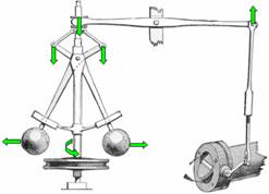
Automatic regulation by analog
means is possible, (example: the flyball governor of a steam engine,) but
hardly feasible in a vehicle of such a small scale. |
Fig.: Kino
/ public domain via Wikipedia |
|||||||||
|
Driving along a track oval, you may
notice that at a certain distance from the feed-in, the train slows down
somewhat, to become faster again as it gets closer to the feed-in again. Reason: the transition resistance
between track pieces accumulates, lowering the voltage with each connector.
With an analog measuring device, this is difficult to measure, unless you
have one that is very good and thus very expensive. Here, we have one of the
advantages of digital measuring technology. If we lay tracks across a hill, the vehicle will slow down driving
uphill, accelerating when going downhill. Finding: the speed of a conventionally controlled
vehicle is influenced by the driveway. In conclusion, you may say: The manual
operation of a model train “feels analog”. Automation of functions
by conventional means (my objective) Even on a small layout, running
two trains simultaneously without accidents requires a certain amount of
concentration. That is why Märklin has thought up and published ideas for
automation early on and has equipped signals with the necessary switching
contacts. The basic idea behind founding the
group was to raise awareness for these possibilities, make practical use of
them, refine them, and carry them to extremes. |
||||||||||
|
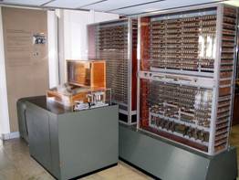
Note: in 1941, Konrad Zuse built the
world’s first working computer, the Z3. It worked with relays, basically
elements like the Märklin universal remote controller. The Z3 is considered
the starting point of digital technology! |
|
|||||||||
|
I have heard it said that since
relays know only “on” and “off”, 0 and 1, they were digital. Would that mean
the Märklin universal remote control is a digital component? What, then, with
turnouts and signals, which work the same way? That would also mean: Only when a button is pushed
manually, and the circuit, thus closed, activates the solenoid coil, changing
the signal aspect, this would be “analog”, conventional. If a vehicle drives over a contact
track, thus closing the circuit with the same result, this would be process
control, thus digital, even more so if other relays, forming dependencies
like turnout directions and track occupancy were part of the circuit. So, if we want to achieve
automation with relays, we have to wave the term analog
goodbye, but must NOT use the term digital
either. Märklin calls it conventional.
I am calling it also electromechanical
and in my sense, the sense of
the group and this homepage. The 1955 Märklin signal booklet describes
several versions of block signaling controls,
with contact tracks and double coil signals, and automatic train running
control. Back in the day, the average model train enthusiast knew nothing
else and would thus not have used the term analog,
let alone digital. I consider a block signaling control,
only consisting of trainoperated contacts and electrically switched signals
to be electromechanical and in my sense and thus in the sense of the
group, and this homepage. The electromechanical control of a
station on a single-track line, on which trains automatically meet without
colliding, I consider to be in my sense
and thus in the sense of my group and this homepage. The electromechanical control of a
hidden fiddle yard with quite a few tracks, in which the arriving train
automatically starts the neighboring next unit, I consider to be in my sense and therefore in the
sense of my group and this homepage. Also, the manual operation of
turnouts and signals can be simplified by smartly designed circuits and the
use of relays, the number of buttons to be operated can be drastically
reduced. As an example I would like to mention the relay switch towers of the
Deutsche Bahn. Hardly anyone would think of calling these digital. So I also
consider circuits in this scope as in my sense
and therefore in the sense of my group and this homepage. If a model railroader has his
layout controlled by cabinets full of relays, with telephone dials and the
like, we would like to see that in my group and I consider that in my sense and therefore in the
sense of my group and this homepage. Semiconductors are common in
conventional model railroad layouts. Without diodes and transistors, many
things would be impossible or difficult to do. We need them, so they are
permissible. Electronic components of
well-known manufacturers which are built up using semiconductor elements and
relays, e.g. for smooth starting and braking by appropriate control of the
traction voltage or (superfluously) for the fiddle yard control or the block
control or the electronic universal remote switch 7244 or ... or ... I
consider to be in my sense and thus in the sense of my group and this homepage. Activating a turnout with a servo
drive, if the drive with its control is considered as a functional unit and
is set straight and branching via two switching contacts, I consider as in my sense and thus in the sense of my group
and this homepage. Analogously, this applies to signals moved with
servo drives, shed gates, turntables, animated figures, etc. The inner (digital)
structure of a functional unit is basically of no interest to us if the unit
acts from and to the outside like an electromechanical device, one could also
build it electromechanically, albeit with immensely greater effort. Control centers The larger the layout becomes, the
more drives have to be moved, the more complicated the interrelationships
become, the greater the number of controlling components and their wiring. Here, it makes perfect sense to
think outside the box: Industrial machine tools have
always required regularly recurring control operations to be carried out. In
1969, the programmable logic controller (PLC) was invented for this purpose,
a switching mechanism programmable via groups of switches or later digitally,
which can switch functions of the connected machine on and off depending on
the activation of contacts in the machine. One of the inventors "...
resisted the name computer. He saw this as endangering acceptance among the
control specialists who had been working up to that time." I regard PLC
in this form as, in the effect, nothing else but a highly complex relay
switchgear, and thus to be in my sense and
thus in the sense of my group and this homepage. I would now like to return to the
differences between the so-called “digital” and the so-called “analog” model
railroad. The operating principle of the
digital model railroad: Theoretically, there are only two
lines leading to the track and, thus, to all signals and turnouts on the
digital Märklin model railroad. (In real life, there are several more...). A command, similar to a Morse
code, is sent to this pair of wires. All decoders read it. The message starts
with the name of the unit which the message is addressed to. Turnouts and
signals with other names ignore the message; the one turnout that is
addressed executes the command that then follows. So this is completely different
from an conventional installation, where each turnout and each signal is
connected to the control device by a whole bundle of wires, and each function
has its own command wire, also when using a PLC! I am in the planning stages of my
next layout. So far, I see no reason to entrust an electronic brain with tasks
instead of the hardwired relays. However, if you include speed
control of the trains, the circuit complexity becomes immense.
That's what we're looking at now: With digital train control, it is
the same as with the turnouts: first the address, then the command. With
locomotives, there can be up to 32 (or more) functions in addition to speed
control. This is of course impossible by electromechanical means – at least
in the locomotive. Märklin introduced a pulse width
control with ~ 200 Hz to the market as early as 1978 in the form of the 6699
“power pack with electronic control for slow speed driving”. This made -
hand-guided - extremely slow driving and gentle starting and braking possible
- by electronic means. The very short switching pulse also made it possible
to minimize the leap when switching the direction of locomotives of the 800
series. In 1983, the 6600 version, which
was expanded to include a shuttle train control system, was released. Here
also an automatic load control, which should keep the speed constant uphill
and downhill, was integrated. Although one is inclined to think of digitally
control with these two devices, they belong to the conventional control and
are thus in my sense and thus in the sense of my group and this homepage. The described speed controls
always require the regulating hand. What would an automatic speed control
with electromechanical control have to look like? A train needs the following
different voltages during its way across the layout: ·
Minimum voltage for the first movement on the
horizontal track, ·
a certain maximum voltage for a realistic maximum
speed in level country, the voltages or increased
voltages necessary to maintain the speed on all the gradients on the layout, ·
the necessary voltages or voltage reductions for all
slopes on the layout. There are a number of ways to
provide these different voltages. Ultimately, they have to be made available
at the right time at the right track section. This can be achieved with
relays or - for a larger number of trains – better with a PLC, or with a PC
with switching interface. These only replace the manual operation, which
would be impossible to manage. – However, in the meantime I have found a
concept for an easily understandable relay control; it should work without a
computer after all... For the acceleration and
deceleration processes, there are ready-made components based on
semiconductors or instructions for home-made circuits, switched on via the
control system. This, too, I consider to be in my sense and thus in the sense of my group
and this homepage. Sounds can be played from
loudspeakers connected to a sound unit at the specific locations of the
layout, and triggered by the locomotive or the controller. Moving sounds can
be controlled as stereo or quadraphonic events (see Miniatur Wunderland at All this is one of the basic ideas
for the founding of my group and thus also of this homepage. Everything (?) that can
be done digitally can somehow also be achieved by "analog", no,
conventional means... |
||||||||||
|
Contact: Mail |
||||||||||