|
|
|
|||||||||||||||||||||||
|
The Prototype Märklin-H0-Knowledge Layout-Building Modelstock |
|
|||||||||||||||||||||||
|
A: The very first
basic knowlege about conventionally controlled Märklin H0 model railways A14m:
Track branches, track connections |
|
|||||||||||||||||||||||
|
state: 12.05.2024 10:05 |
|
|||||||||||||||||||||||
|
Contact:
Mail |
|
|||||||||||||||||||||||
|
Preface Since
I almost exclusively own Märklin metal tracks (M-tracks) and some Märklin
model tracks, this page only describes the turnouts of these systems. The
description of M-track crossings, double crossings, turntables and the
transfer table you find in separate pages. Here
I am only describing turnouts with central conductor stud contacts. The
mentioned radii are related to the center conductor. The
detailed naming of the numbers should help you to identify the turnouts
offered. Planning
programs also list these numbers. (I hope I researched everything correctly
...) I
repeat some things in the sections so that the information is complete there. So
that we speak of the same: Terms
around the turnouts Märklin
published a beautiful book in 1972:
Unfortunately,
the turnout variants that came out after 1975, the numbers 5137 to 39, are
missing. I
refer to this book in the following. Therefore it makes sense for you to open
this link in a second window. Almost all the dimensions of the M-rails can be
found in this book. In
1982 a new book came out that brought other interesting information. It also
shows the turnouts 5137 to 39:
Spare
parts lists for the newer turnouts and more
Historical overview Märklin
M tracks with stud contacts appeared for the first time parallel to the M
tracks with a continuous central conductor rail no. 3600 xx in the 1953
catalog in the form of "model tracks" no. 3800 xx and no. 3900 xx
with very large radii, which are still a specialty in the Märklin system and
are expensive. Beginning
in the catalog of 1956 are the M-stud contact tracks with the radii 360 mm
and 286 mm to be found as the third variant, initially as no. 3601 xx. From
1957 the M-rails of the normal circle radius 360 mm were then numbered 51xx
(the arc radius 286mm no. 5120) and the new parallel circle radius 437.4 mm
with numbers 52xx. In
the years 1969 - 1992 Märklin produced a reduced and technically partially
simplified range under the brand name “Primex”, which was sold outside the
specialist trade and without advice, e.g. in warehouses. The
M-rails disappeared from the range in 2000. In
more detail (german) in maerklin-h0-forum.de In
the catalogs only the turnout pairs were numbered. Because track planning
programs also name the individual numbers, they are listed below. Manual turnouts
(without remote control) Normal circle manual turnouts Geometry: straight
track 180mm long, The
opposite curve is the track section 5100 (radius 360 mm, curve angle 30°),
with which the direction of the branching track is brought back parallel to
the main track. |
|
|||||||||||||||||||||||
|
|
||||||||||||||||||||||||
|
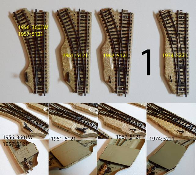
Variants: A)
in picture 1 on the far left, Metal
lever, small bulge of the ballast bed around the adjusting lever |
|
|||||||||||||||||||||||
|
|
1956 |
1957
to 1960 |
|
|||||||||||||||||||||
|
1 pair |
no 3601 W |
no 5121 |
|
|||||||||||||||||||||
|
left
hand turnout |
no 3601 WL |
no 5122 |
|
|||||||||||||||||||||
|
right
hand turnout |
no 3601 WR |
no 5123 |
|
|||||||||||||||||||||
|
B)
in picture 1 second from the left, Metal
lever, shape of the ballast bed like the electromagnetic turnout |
|
|||||||||||||||||||||||
|
|
1961 to 1966 |
|
|
|||||||||||||||||||||
|
1 pair |
no 5121 |
|
|
|||||||||||||||||||||
|
left
hand turnout |
no 5122 |
|
|
|||||||||||||||||||||
|
right
hand turnout |
no 5123 |
|
|
|||||||||||||||||||||
|
C)
in picture 1 third from the left, Plastic
lever, shape of the ballast bed like the electromagnetic turnout |
|
|||||||||||||||||||||||
|
|
1967 to 2000 |
|
|
|||||||||||||||||||||
|
1 pair |
no 5121 |
|
|
|||||||||||||||||||||
|
left
hand turnout |
no 5122 |
|
|
|||||||||||||||||||||
|
right
hand turnout |
no 5123 |
|
|
|||||||||||||||||||||
|
Parallel circle manual turnouts Not
included in the Märklin 0390 book. Geometry: straight
track 180mm long, Supplement
with track section no. 5205 (R2, angle 5°43' ≈ 5.7°) to the entire
curved track no. 5200 (R2, angle 30°). The
opposite curve is track no. 5206 (R2, angle 24°17' ≈ 24.3°), with which
the direction of the branching track is brought back parallel to the main
track. Attention: Variants: right
in picture 1, plastic
lever, shape of the ballast bed like the electromagnetic turnout |
|
|||||||||||||||||||||||
|
|
1974 to 2000 |
|
|
|||||||||||||||||||||
|
1 pair |
Märklin no 5221 |
|
|
|||||||||||||||||||||
|
left
hand turnout |
Märklin no 5222 |
|
|
|||||||||||||||||||||
|
right
hand turnout |
Märklin no 5223 |
|
|
|||||||||||||||||||||
|
(labeled as 5202/5221. The same blanks were used for the
manual turnout and the electromagnetic turnout,
therefore both numbers are on the turnout.) |
|
|||||||||||||||||||||||
|
|
1969 to 1992 |
|
|
|||||||||||||||||||||
|
1 pair |
Primex no 5043 |
|
|
|||||||||||||||||||||
|
1 pair
with 2 opposite curves |
Primex no 5033 |
|
|
|||||||||||||||||||||
|
(Labeled
as 5039. The same blanks were used for the manual turnout and the
electromagnetic turnout; therefore the number of the E-turnout is also on the
manual turnout.) |
|
|||||||||||||||||||||||
|
Function of the manual turnouts |
|
|||||||||||||||||||||||
|
The
hand lever acts on an angle lever that pulls the turnout blades into the
other position via a tension spring (Märklin spare part no. 353080). The
turnout tongues are resiliently on one or the other stock rail. |
|
|
||||||||||||||||||||||
|
A
vehicle wheel can overcome this spring force and cut open the turnout. The
plastic levers are a bit delicate (caution: risk of breakage if the mechanism
gets stuck). Picture
2 shows a hand turnout with a metal hand lever in both positions at the top
and a plastic hand lever at the bottom. Maintenance of all turnouts The
turnout blades rotate around a rivet. This bearing should be clean. Lubrication
is not recommended, as this can lead to the accumulation of dust and sticking
of the bearing. In
order to access the drive mechanism, the base plate of the turnout must be
removed. Look before-hand exactly where the sheet metal reaches into the
track structure and where it reaches over on the outside, where there are
latches. Then you will get the sheet back into its place later. It
is noticeable that the spring acts at different angles on the turnout points
in the two turnout positions. According to my technical understanding, the
pressure forces are different. It should be like that, it will be the result
of a long development, so it should be correct. With the very old manual
turnouts, there are two alternative grooves on the angle lever for hooking in
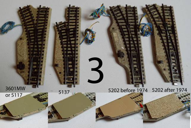
the spring, with the electric turnouts then only one. Simple electromagnetically operated turnouts Normal radius turnouts Geometry: (Picture
3, the left two) Variants: |
|
|||||||||||||||||||||||
|
|
|
|||||||||||||||||||||||
|
A)
left in picture 3, Arc
angle 30°, |
|
|||||||||||||||||||||||
|
|
1956 |
1957 to 1974 |
|
|||||||||||||||||||||
|
1 pair |
no 3601MW |
no
5117 |
|
|||||||||||||||||||||
|
left
hand turnout |
no 3601MWL |
no
5118 |
|
|||||||||||||||||||||
|
right
hand turnout |
no 3601MWR |
no
5119 |
|
|||||||||||||||||||||
|
With
this turnout there is a risk of collision with the large lantern on long wagons
(bogie spacing over 18 cm and with low-hanging attachments in the middle of
the wagon). In this case, only dismantling the lantern or replacing the
turnout with variant B) of this geometry helps. However, very long wagons can
also collide with them. The
opposite curve is the track section no. 5100 (R1, angle 30°), with which the
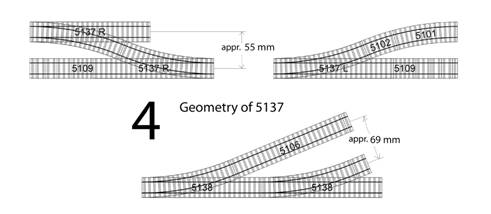
direction of the branching track is brought back parallel to the main track. B)
in picture 3 second from the left. Not included in
the Märklin 0390 book, but in the Märklin 0700 book. Arch
angle 22.5°, small lantern (caps tend to come off) This
variant can be supplemented with track no. 5102 (R1, 7.5° angle) to no. 5117.
Opposite
curve is the combination of track section no. 5102 (R1, angle 7.5°) and no.
5101 (R1, angle 15°), with which the direction of the branching track is
brought back parallel to the main track. |
|
|||||||||||||||||||||||
|
|
1975 to 2000 |
2000
to 2001 digital |
|
|||||||||||||||||||||
|
1 pair |
no 5137 |
no
2604 |
|
|||||||||||||||||||||
|
left
hand turnout |
no 5138 |
|
|
|||||||||||||||||||||
|
right
hand turnout |
no 5139 |
|
|
|||||||||||||||||||||
|
This
variant results in interesting possibilities that can be found in the Märklin 0700 book. |
|
|||||||||||||||||||||||
|
|
|
|||||||||||||||||||||||
|
Parallel
radius turnouts Geometry: (Picture
3, the right two) Supplement
with track section no. 5205 (R2, angle 5°43' ≈ 5.7°) to the entire
curved track no. 5200 (R2, angle 30°). The
opposite curve is track no. 5206 (R2, angle 24°17' ≈ 24.3°), with which
the direction of the branching track is brought back parallel to the main track.
Attention: Variants: A) in picture 3 third from the left,
big
lantern |
|
|||||||||||||||||||||||
|
|
1957 to 1973 |
|
|
|||||||||||||||||||||
|
1 pair |
no 5202 |
|
|
|||||||||||||||||||||
|
left
hand turnout |
no 5203 |
|
|
|||||||||||||||||||||
|
right
hand turnout |
no 5204 |
|
|
|||||||||||||||||||||
|
With
this turnout there is a risk of collision with the large lantern on very long
cars and with low-hanging attachments in the middle of the car. In
this case, only the dismantling of the lantern or the exchange of the turnout
for variant B) of this geometry helps. However, very long wagons can also
collide with them. B)
in picture 3 fourth from the left, small
lantern (caps tend to come off) |
|
|||||||||||||||||||||||
|
|
1974 to 2000 |
|
|
|||||||||||||||||||||
|
1 pair |
no 5202 |
|
|
|||||||||||||||||||||
|
left
hand turnout |
no 5203 |
|
|
|||||||||||||||||||||
|
right
hand turnout |
no 5204 |
|
|
|||||||||||||||||||||
|
1976
to 1992 also: Function of the electromagnetic turnouts |
|
|||||||||||||||||||||||
|
The
armature driver acts on an angle lever that pulls the turnout blades into the
other position via a tension spring (Märklin spare part no. 353080). |
|
|
||||||||||||||||||||||
|
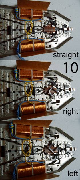
The
turnout tongues are resiliently on one or the other stock rail. A
vehicle wheel can overcome this spring force and cut open the turnout. Picture
5 shows an older turnout in both of its positions above, and a newer one
below. A
simple electromagnetic turnout has 3 connection lines: 1st Via the yellow 16V line
from the L connection of the transformer, leads to three points: 2nd Ground for the selenoid
straight ahead, via the blue wire with the green plug, 3rd Ground for the selenoid
branching off via the blue wire with the red plug. Ground
for the lamp comes from the track. For
the turnouts function, it is sufficient to apply 16 V to yellow and to
connect ground to one of the blue lines using a push button contact (!), E.g.
of a control panel no. 7072. See
also the article “The evolution of
the Märklin control panels” The
double selenoids do not tolerate longer continuous voltage, The
double selenoid alternately pulls the armature inside back and forth, which
moves the mechanics via the driver arm. For
the lighting of the lantern, ground must be on the track structure, i.e. the
turnout must be built into the track. If
you want to turn off the lanterns, i.e. only let them light up at night, you
cut the short yellow wire be-tween the selenoid and the lamp and extend it to
a switch with 16 V. General manual
"Electrc Turnouts" Maintenance of the turnouts see under manual turnout above. The
magnetic drive should also be kept clean and free of grease. |
|
|||||||||||||||||||||||
|
Spare
Parts: Spring
No. 353080 Bulb
No. 600000 The
bulb of the large turnout lantern had a longer glass body than the later ones
(the short ones were developed later.) The big ones don't fit into the
turnouts with a small lantern. Picture
6: The light bulbs in comparison For
turnouts with small lanterns see also spare parts list |
|
|
||||||||||||||||||||||
|
Model track turnouts |
|
|||||||||||||||||||||||
|
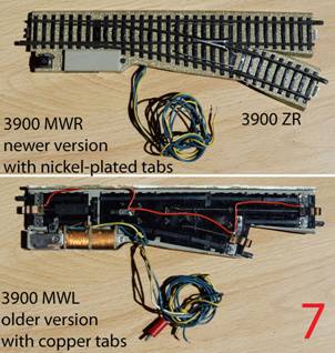
Geometry: straight
track 224 mm long, branching track radius 585 mm, a little more than R4, Arc
angle 16.875° = 16°52’30" = 16 7/8°, There
are three additional tracks to continue the branch, because normal tracks do
not fit, collide with the bedding (picture 7a): |
|
|
||||||||||||||||||||||
|
1st No. 3900 ZD 2nd No. 3900 ZR |
|
|
||||||||||||||||||||||
|
3rd No. 3900 ZL The
geometric possibilities and restrictions with the model track system as well
as the technical details are presented in the article “Märklin
model tracks - a closer look at these exotics”. Variants: |
|
|||||||||||||||||||||||
|
|
1953
to 1956 |
1957 |
|
|||||||||||||||||||||
|
1 pair |
no 3900 MW |
no
5064 |
|
|||||||||||||||||||||
|
left
hand turnout |
no 3900 MWL |
no
? |
|
|||||||||||||||||||||
|
right
hand turnout |
no 3900 MWR |
no
? |
|
|||||||||||||||||||||
|
Initially,
the model tracks were made with narrow copper tongues on the central
conductor, later with nickel-plated wide tongues. Funktion: A
long spring wire is rigidly attached to the magnet armature and, thanks to
its angled shape, pushes a slide back and forth. The individually rotatable
turnout tongues are guided on the slide. Incidentally, what has been said
about the other points applies. Maintenance see under manual turnout above. The
magnetic drive should also be kept clean and free of grease. Special turnouts Inner curved turnout |
|
|||||||||||||||||||||||
|
Geometry: Main
track: straight track 77.4 mm with subsequent radius 360 mm (R1) with a curve
angle of 30°, branching track radius 360 mm (R1) arc angle 30° The
branching track s parallel to the man track, so no additional track section
or counter curve s reuired. However,
the track spacing is extremely small (see Märklin 0390 book, page 3) |
|
|
||||||||||||||||||||||
|
Variants: small
lantern (caps tend to come off) |
|
|||||||||||||||||||||||
|
|
1964 to 2000 |
|
|
|||||||||||||||||||||
|
1 pair |
no 5140 |
|
|
|||||||||||||||||||||
|
left
hand turnout |
no 5141 |
|
|
|||||||||||||||||||||
|
right
hand turnout |
no 5142 |
|
|
|||||||||||||||||||||
|
Funktion: Like
the simple turnouts Maintenance: see under manual turnouts above. The
magnetic drive should also be kept clean and free of grease. |
|
|||||||||||||||||||||||
|
Symmetrical two-sided double turnout Geometry: straight
track 180mm long, Extension
of the branch with track section 5205 (5°43’
≈ 5.7°) to the entire curved track 5200 (30°). The
opposite curve is track section 5206 (24°17' ≈ 24.3°), with which one
brings the direction of the branching track parallel to the main track again.
Attention: Variants: 1969
to 2000: no. 5214 Funktion: Like
the simple turnouts, but twice. The
two angle levers can collide overlap, hook. It is therefore very important
that you always go straight from a branch position and only then to the other
branch. |
|
|
||||||||||||||||||||||
|
This turnout has 5 connection lines:
The
two green ones switch to straight, then you can branch with one of the red
ones be switched. A
simple circuit was shown in the german Märklin-Magazin 3/1971
(picture 11) that prevents the collision. In
the german Märklin magazine 2/1975 the installation of a mechanical override
was shown (picture 12). Maintenance: see under manual turnout above. The
magnetic drive should also be kept clean and free of grease. |
|
|||||||||||||||||||||||
|
|
|
|||||||||||||||||||||||
|
|
|
|||||||||||||||||||||||
|
The Prototype Märklin-H0-Knowledge Layout-Building Modelstock |
|
|||||||||||||||||||||||