|
|
|
||||||||||||||||||
|
The Prototype Märklin-H0-Knowledge Layout-Building Modelstock |
|
||||||||||||||||||
|
A: The very first
basic knowlege about conventionally controlled Märklin H0 model railways A17:
Tracks with functions |
|
||||||||||||||||||
|
Preface This
article is about tracks with function. Sometimes
you don't see this function at first glance. It
is therefore possible that when you buy used tracks you get unwanted parts
that work differently than expected. Since
I almost exclusively own Märklin metal tracks (M tracks), this article
describes the M track sections in detail, but I limit myself to tracks with
stud contacts, i.e. from 1953 onwards. I
describe K and C tracks to the best of my knowledge. The
detailed naming of the numbers should help you to identify or specifically
search for the available tracks. Planning
programs also list these numbers. )* For the production of the M track sections with function described
here, ready-printed standard track section
blanks were branched off during the production process. This is
why the number of the original standard M-track piece is printed on these
special M-track pieces. So that we understand each other correctly: A "track" is made up of the two "rails" that are
attached to the sleepers with the tie plates, scews and washers. I used to say rail to the track too when I was a child... Contact track sections Märklin
had contact tracks in its range from the very beginning of the electric model
railroad. The
idea of the function being triggered by the train was already present in the
clockwork model rail-ways. Funktion We
know that turnouts and signals are switched over via the blue lines by
briefly (!) connecting one of them to ground. You can do this with a hand
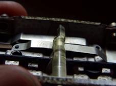
button or with a contact track by a train passing over it. In
the case of the contact track, part of one of the two rails is insulated from
the neighboring rails and from the rail opposite (picture 1). A
conductive)** wheel set rolling over it connects the insulated rail part with
the opposite one, i.e. with ground. A
solenoid connected to the insulated rail section therefore receives an earth
pulse and reacts to it.
)**
Märklin usually equips its models with leading wheelsets. All
other brands usually have isolated wheelsets. If you want to use the function
of the contact tracks, you have to pay attention to conductive wheel sets in
your wagons, if necessary convert them. My page "Wheel sets - swap? If so, why?"
provides more detailed information on this. A
problem with contact rails is that a train STANDING on it closes the contact
as long as it stands there. The solenoids of the turnouts and signals cannot
tolerate this; they get hot and finally burn out. I show a circuit that
prevents this with signals on my page "Protection
against burnout of coils of Märklin signals". Another
problem with contact tracks can be that a locomotive whose wheel sets each
run with one wheel on this insulated rail part only has ground contact via
the other wheel. If the wheels of a locomotive are dirty, this can lead to
engine misfires. You
have to reckon with the fact that the contact provided by the contact track
is not constant as long as a train is travelling over it, due to uneven
pressure on the wheels and dirt in places. If
you want to have constant contact throughout, the contact distance must be at
least slightly greater than the longest wheel set distance (theoretically,
one of the two wheel sets makes contact), preferably longer than the longest
wagon, so that there is significantly more than one wheel set on it. Contact
tracks work regardless of the direction of travel of the train. You
can create a direction-dependent circuit with two contact tracks or assign
different tasks to a contact track depending on the situation, depending on
the direction of travel. I show examples on the pages of the "Circuits
for advanced users - automation of processes" section. |
|
||||||||||||||||||
|
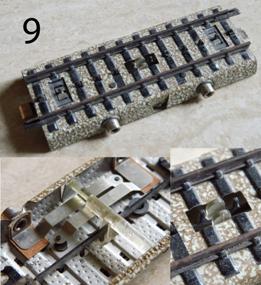
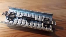
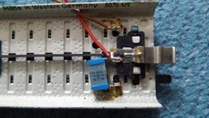
M-contact track sections In the case of M-contact tracks, at
least a part of one rail is attached insulated from the ballast bed. In the picture, the rail section between
the marked joints is insulated from the rest of the track and connected to
the two sockets or the socket. Note: the brown spherical components
(radio interference suppression) on the underside probably do not interfere
with digital operation, as no digital signal flows through them. On the
contrary, they reduce the breakaway spark and thus possible interference in
the high frequency range and burn-in marks on the wheels at higher switching
currents. (No guarantee of completeness and correctness.) |
|
|
|||||||||||||||||
|
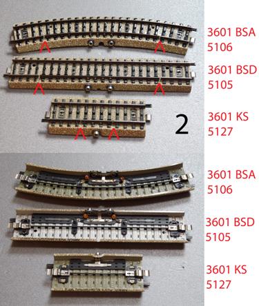
Variants on the picture 2 above: These
variants were created to operate magnetic items (i.e. turnouts, signals,
relays such as the universal remote switch). The frequently heard opinion
that magnetic items should not be operated with contact tracks is wrong! Equally
wrong is the opinion that these variants are intended for railway crossings. M-contakt track section, curved,
radius: 360mm (R1), angle of the arc: 30°, In the catalogue 1956: No. 3601 BSA, labelled 3601 A )* M-contakt track section, straight
180mm long, In the catalogue 1956: No. 3601 BSD, labelled 3601 D )* M-contakt track section, straight
90mm long, In the catalogue 1956: No. 3601 KS, labelled 3601 D
1/2 )* 1957 to 1961: No. 5127, labelled
5107 1/2 )* The idea behind this "warning
cross" set is that each leading wheel set of the train generates a
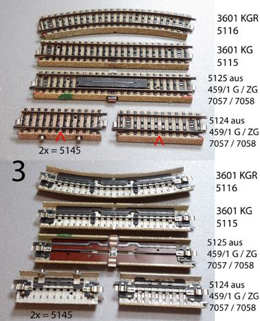
flashing pulse (theoretically). Picture 3: In 1956, an (arbitrarily) expandable
contact track system was developed for the automatic level crossing. The two barriers are activated and
closed by contact track no. 5125. The coils of the level crossing are
designed for continuous operation, so the current can and should be effective
for longer. The barrier is closed as long as the contact is closed. The contact track can be extended on
both sides of the level crossing with contact tracks no. 5115 and no. 5116.
The ends of the contact section each form a contact section end piece no.
5124. My page "Control of Märklin level
crossings" deals with the problems with the automatic level
crossings and the possible solutions.
|
|
||||||||||||||||||
|
In the picture, from top to bottom: M-contakt track section curved, in the catalogue 1956: No. 3601 KGR, labelled 3601 A )* M-contakt track section, straight
180mm long, in the catalogue 1956: No. 3601 KG, labelled 3601 D )* There are two options for the road
section of the railway crossing: 1st M-contact track section straight
180mm long, In the manual of the grade crossing 1956: No. unknown, labelled 3601 D )* Available only in set "Fully
automatic grade crossing", In the catalogue 1956: No. 459/1 G, 2nd M-contact track section straight
90mm long, |
|
||||||||||||||||||
|
In the catalogue 1974 to 2000: No. unknown Available only in set "Fully
automatic grade crossing", In the catalog 1974 to 2000: No. 7292 |
|
|
|||||||||||||||||
|
A contact section is limited on both
sides by one In the catalogue 1956: No. unknown, labelled 3601 D
1/2 )* Available only In the catalogue 1956: No. 459/1 G In order to build any contact
section independent of the level crossing, contact section end pieces with
connection sockets were created. They were offered in a set of 2. In the catalogue 1957 to 2000: No. 5145, labelled
5107 1/2 )* |
|
||||||||||||||||||
|
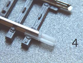
K contact tracks In the case of K-rails, the rails
are insulated from the start and fastened to the sleeper grid, so that you
only have to prevent contact with the adjacent rails in the case of one rail
(e.g. with insulating rail connectors, which are available in various designs
from Fleischmann and Roco, for example, picture 4) or cut a rail in two
places. The connection to the insulated rail
is achieved with the earth connection no.7500. |
|
|
|||||||||||||||||
|
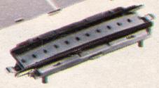
Picture 5: The level crossing for
the K-Track came out in 1974, and with it a contact track system that could
be expanded as required. The level crossing: in the catalogue 1974 to 2013: No. 7592 and the extra parts: in the catalogue 1974 to 2013: No. 7593.
These each contain two K-contact track boundary sections
90mm No. 2295, in which a rail is divided in the middle and the parts are not
electrically connected. Two end pieces and any number of
standard tracks result in a contact route. The rails, isolated from the general
mass, must form an uninterrupted chain. For the road section of the level
crossing there is a 90mm track section with lateral plug-in connections for
the road ramps and filling between the rails. C contact tracks |
|
||||||||||||||||||
|
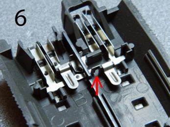
In the case of C-tracks, both rails
are also attached to the track bed in an isolated manner, but are connected
to a bridge on the underside at the ends of the track section. These bridges can be separated at a
prepared point (arrow). The ground connections at the two
ends of the track section are then no longer connected to both, but only to
one rail each. |
|
|
|||||||||||||||||
|
Contact with the neighbouring tracks
is prevented with the insulating cap no.74030. The rails themselves do not touch at
the transition from track section to track section. In 2000, the first level crossing
for the C-track came out and with it a freely expandable contact track
system. The level crossing: in the catalog 2000 to 2013: No. 74920, and the extra parts: in the catalog 2000 until today: No. 74930. These each contain two C-contact
track end pieces 94.2mm no. 24995 (no. for the pair), where one rail is split
in the centre and the parts are not electrically connected. Two end pieces and any number of
normal tracks whose rail connections have been separated (picture 6) form a
contact section. The rails insulated from the general earth must form an
uninterrupted chain. For the road section of the level
crossing there is a 94.2mm track section without a known number with lateral
plug-in connections for the road ramps and filling between the rails. Detailed pictures of it can be found
at lokmuseum.de. And here is a more detailed
description (german) at modellbahnkeller.eu Modellgleis contact track sections |
|
||||||||||||||||||
|
On the model tracks from 1953 to
1957, the rails are attached to the plastic sleepers in isolation and on some
track sections are only connected once by a bridge. |
|
|
|||||||||||||||||
|
There are ready-made contact track
pieces: Modellgleis contact track section
straight, 224mm long, Modellgleis contact track section
courved, Modellgleis contact track section
courved, |
|
|
|||||||||||||||||
|
You can convert any model track by
separating the mentioned bridge and using insulating rail connectors. In this
way the track becomes completely a contact track. Alternatively, you can cut a rail,
in which case you have to separate the metal strip on the bottom in the same
way. Detailed description: “Märklin
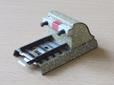
model railway tracks - a closer look at these exotics”. Switching track sections It can be seen as a disadvantage
that contact tracks react to every leading wheel set and in both directions.
That is why Märklin invented the switching track. In the middle of the switching
track, under the sleepers, there is a shaft with two cams that protrude from
the track up to the right and left next to the point contacts. Each current collector shoe moving
over it turns the shaft. Depending on the direction, one of
two switching contacts is closed via an eccentric, one for each direction. This leads ground to one of the two
connection sockets. So you only get a
direction-dependent signal from the current collector shoe driving past. The mechanics of the M switching
tracks are not always reliable. The return springs can be reinforced, but
this can lead to the current collector shoe being lifted and the current flow
being briefly interrupted. M-track switching track sections |
|
||||||||||||||||||
|
Video of the mechanism Click on the picture! |
|
|
|||||||||||||||||
|
Variants: M-track switching track section
straight, 90mm long, M-track switching track section
courved, M-track switching track section
courved, |
|
|
|||||||||||||||||
|
K-track switching track sections Variants: K-track switching track section
straight, 90mm long, K-track switching track section
courved, K-track switching track section
courved, C-track switching track sections Variants: C-track switching track section
straight, 94,2mm long, C-track switching track section
courved, C-track switching track section
courved, Separating track sections Usually you separate your circuits
by isolating the plug connection between track pieces. It is therefore
surprising that there are sections of track with an interruption in the
center conductor. In 1971 two light signals appeared.
source: Märklin catalog 1976 one for M-trackwith the no. 7339 and one for K trackwith the no.7539. |
|
||||||||||||||||||
|
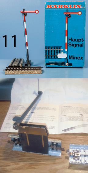
And the home signal No. 7400 in |
|
|
|||||||||||||||||
|
These signals are set on site via a
slide switch, so no remote control. |
|
||||||||||||||||||
|
The central conductor is interrupted
(stop) or connected (travel) in the 90mm track section attached to the
signal. The traction current is fed in behind
the signal and the area in front of the signal is switched. To limit the switched area, the
signal is supplied with a 90mm section of track with an interrupted central
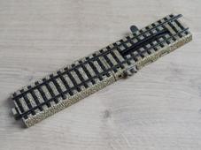
conductor - the separating track. The separating track has no known
number of its own, but the M track section is labelled 5107 1/2 )*. |
|
|
|||||||||||||||||
|
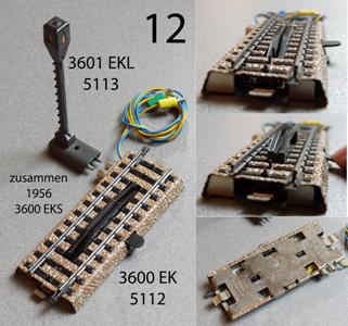
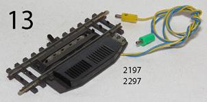
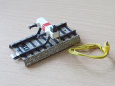
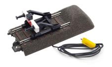
Uncoupling track sections Most variants of the train couplings
can be unlocked by lifting them from below. The uncoupling track sections are
used for remote-controlled uncoupling. A uncoupling track section has two
connection lines: -
yellow cable with yellow plug for connection to the light connection of the
transformer, -
blue cable with green plug for connection to ground via a momentary contact,
e.g. a control desk. As long as the blue wire is connected
to ground, a bar is raised in the middle of the track so that any couplings
standing or moving over it are unlocked. The drive is designed for 16V
alternating current, but also works with significantly lower voltage. You can also use direct current.
This makes the noise much less. M-track uncoupling track section (picture 12) length 90mm, In the catalogue1956: In the catalogue 1957 to 2000:
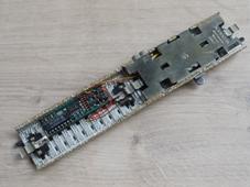
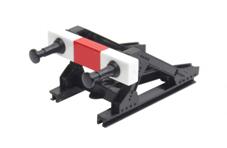
In the period from 1986 to 1990,
Westermann Lehrmittelverlag sold a digital demonstration set in 2 cases under
the name TRAIN-ING. Remaining stocks were later sold by Märklin itself under
the number 6232 for the set and individually as 6201 and 6202. This set also included a digitised
uncoupling track. As the decoder could not be accommodated in the uncoupling
track section, half a straight track section 5107 was permanently connected
to the uncoupling track section. Both pieces of track are labelled 5107 1/2 )*. The cover of the decoder is missing
on my example.
This uncoupling track is unusable in
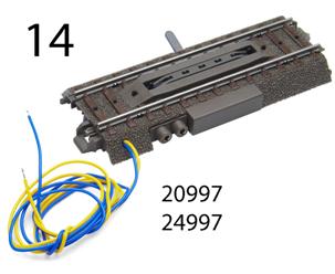
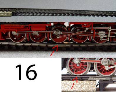
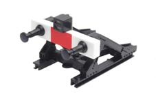
a conventional layout. You can read the whole story at tischbahn.de. K-track uncoupling track section (picture 13) length 90mm, In the catalogue There are 2 cable clamps on the
front of the drive. The assignment is identical to the connection cables. So
you could - as with the M track uncoupling track - connect a control light.
C-track uncoupling track section (picture 14) length 94,2mm, In the catalogue Light mast no. 74997, apparently
identical to no. 5113 from the M Track programme.
|
|
||||||||||||||||||
|
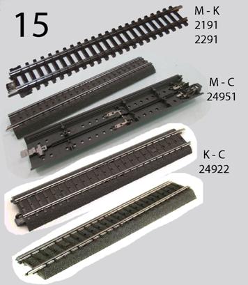
Adapter track sections (picture 15) Transition between M-Track and
K-Track, Transition between M-Track and
C-Track, Transition between M-Track and
Alpha-Track Transition between K-Track and
C-Track, |
|
||||||||||||||||||
|
Critical note: The disadvantage is that Märklin
only supplies the transition track pieces as straight track pieces and only
in these lengths. And: The transition tracks to the K track
must rise to 180mm from 5.2mm (K) to 10.3mm (C) or 11mm (M), without a smooth
transition! |
|
||||||||||||||||||
|
This means that, for example, a
multi-axle steam locomotive can lift off at the upper break point with the
traction tire axle and no longer has any propulsion or lift off at the lower
break point with the central axles. |
|
|
|||||||||||||||||
|
Couplings can fall out and wagons
can derail. Problem solution: Underlay the K
tracks on the transition track and slowly lower them. The radio suppression track section There are always sparks at the
collector of the locomotive engine and often between the wheel and the rail. These sparks emit radio waves that -
at least in the past - had a sensitive impact on radio and television
reception. In the age of digital media, this is
no longer so noticeable. The interference in the VHF and
analog television range is suppressed by the interference suppression kit
built into the locomotive. |
|
||||||||||||||||||
|
In 1959, Märklin created a curved
section of track with a capacitor to extinguish radio waves in the medium and
long wave range. Radius 360mm (R1), |
|
|
|||||||||||||||||
|
As capacitors age, it is likely that
they will no longer work and there may be a risk of fire. Therefore: do not
use or unsolder the capacitor and dispose of it as hazardous waste. Between 1971 and 1973 radio
interference suppression was not mentioned in the catalogue. |
|
||||||||||||||||||
|
In 1974 a straight current feeder
section with built-in suppression capacitor appeared, 180mm long. in the Primex catalogue |
|
|
|||||||||||||||||
|
The suppression capacitor shown is a
coincidental example. The design can vary. A curved current feeder section with
radio interference suppression was never in the program. For the sake of completeness: The capacitors must be removed
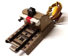
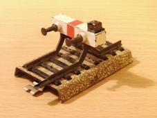
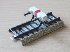
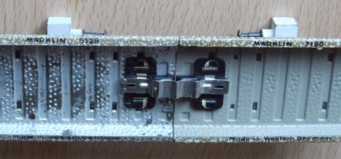
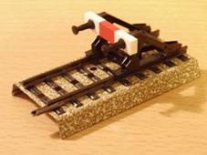
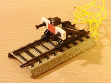
before starting a digital drive! Buffer stops Although the M-track buffer stops
no. 7190/7191 are unmistakable, they are made from blanks of the straight
70mm track section 5129 and usually bear its number. But here there is the
only exception to the rule that I know of: for a short time there was
apparently an attempt to print the correct number on the buffer stops. Thus,
in the version from 1959 to 1974, there are examples with the printed number
7190. For the sake of completeness: |
|
||||||||||||||||||
|
The first M-track
buffer stop for the 00/H0 M track appeared in 1939. Buffer stop "...in concrete
style...", in the catalogue |
|
|
|||||||||||||||||
|
With additional locking signal: in the catalogue |
|
|
|||||||||||||||||
|
A new buffer stop with illuminated
blocking signal based on the straight track section no. 3900 D 1/4 appeared
with the model track: in the catalogue |
|
|
|||||||||||||||||
|
The same buffer stop design was then
adopted for the M tracks with
point contacts on the basis of straight track section no. 5129. |
|
|
|||||||||||||||||
|
In the catalogue
|
|
||||||||||||||||||
|
The buffer stop no. 7059 based on
the model track was replaced by one based on the 70mm M track. In the catalogue |
|
|
|||||||||||||||||
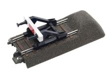
|
With the K track,
a plastic buffer stop appeared for mounting on the K track, but in principle
it fits on any H0 track. |
|
||||||||||||||||||
|
K-track buffer stop: in the catalogue |
|
|
|||||||||||||||||
|
The K-track buffer stop with
blocking signal was significantly delayed: in the catalogue |
|
|
|||||||||||||||||
|
Using the K-track buffer stop, a new
generation of buffer stops was then created for the M-track on the basis of
the 70mm track section while retaining the numbers. in the catalogue Due to the absence of the centre
conductor lug on this version, the connection to the next track section is
extremely poor. |
|
||||||||||||||||||
|
Variant up to 1981 Horizontal foot plates, no openings
for centre conductor. |
|
|
|||||||||||||||||
|
Variant from 1982 Folded foot plates, openings for
non-existent centre conductor. |
|
|
|||||||||||||||||
|
And the version with blocking signal
(much earlier than the K-track version): in the catalogue |
|
|
|||||||||||||||||
|
The C-track
buffer stops: |
|
||||||||||||||||||
|
in the catalogue |
|
|
|||||||||||||||||
|
With locking signal: in the catalogue |
|
|
|||||||||||||||||
|
|
|
||||||||||||||||||
|
The Prototype Märklin-H0-Knowledge Layout-Building Modelstock |
|
||||||||||||||||||
|
state: 27.01.2024 19:24 |
|
||||||||||||||||||
|
Contact:
Mail |
|
||||||||||||||||||