|
|
|||
|
The Prototype Märklin-H0-Knowledge Layout-Building Modelstock |
|||
|
A: The very first
basic knowlege about conventionally controlled Märklin H0 model railways A16:
All around and back and forth - |
|||
|
state: 07.02.2024 15:35 |
|||
|
Contact: Mail |
|||
|
Historical basics As
long as steam locomotives were in service, there was an operational need to
turn the locomotive, especially in the case of tender locomotives, because
unlike tender locomotives, they were not allowed to travel backwards with the
tender in front as fast as forwards. |
|||
|
Turning
was possible with a turning loop (very large), a track triangle (quite large)
or even with a turntable. |
|
||
|
In
the first stations, almost all of which were terminus stations, the platform
tracks often ended at a turntable, which replaced a structurally longer turnout
line and at the same time enabled the locomotive to turn. Some tracks also
led to the wagon depots via turntables. It
was soon realised that a turntable was a very space-saving means of
distributing the locomotives to the sidings. The engine sheds were therefore
built in an arc around a turntable. There
were also smaller turntables in the centre of domed engine sheds. Examples |
|
||
|
And
in industrial plants, there were wagon turntables in places where wagons had
to be brought around the corner but no track curve was possible. With
the end of steam traction in 1976, the maintenance of turntables became
superfluous; they were removed in many places, but sometimes even fitted with
a contact wire spider and reused for electric locomotives. You
might think that with European electric and diesel locomotives it doesn't
matter which direction they run in, as they often appear to be symmetrical at
first glance. However: In
the magazine "Modelleisenbahner" May 1995 you can read in a report
about the work of an engine driver: "... He must tell the turntable
attendant his train number and the driver's cab with which he wants to leave.
As the class 216 has all the display and monitoring instruments in cab 2,
heavy trains should be driven from there. If there are problems, the driver
does not need to walk through the engine room. ..." Turntables from
Märklin Märklin
built turntables for the various track systems right from the start of model
railway production. The
first turntable that was compatible with the M track system appeared in the
1939 catalogue under the number 410M with 3 sidings and 3 access tracks. A
motorless version of this turntable bore the number 410H. The
turntable described in more detail below appeared in 1951 as No. 410N, later
7027, with 6 sidings and 4 access tracks. In
1956 a cheap version of this appeared with 3 sidings and 1 access track as
No. 410B, later 7026. In
1991 a new turntable with flexible K-track sidings appeared, a variant of a
Fleischmann turntable. And
in 2019 Märklin presented a new C-track turntable. The "disc
mine", the turntable for the M track |
|||
|
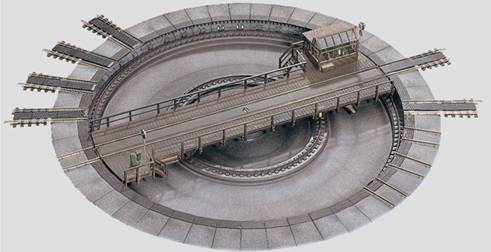
We
will first look at the model from 1951 onwards, which is affectionately
called the "Tellermine" by fans and is still available used in
various colours and in different states of preservation. |
|
||
|
Variants: with
6 sidings and 4 access tracks, with red lamp on the engine house from
1951 to 1956: No. 410 N from
1956: labelled as "Super version" only
1957: No. 7027 with
3 sidings and 1 access track, without lamp labelled
as "standard version" only
1956: No. 410 B only
1957: No. 7026 with
6 sidings and 4 access tracks, without lamp from
1958 to 1993: No. 7186 Hint
for the variant 410 B / 7026 This
turntable has an access road and three shed tracks opposite. This is enough
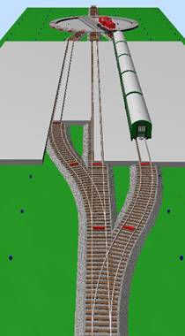
to serve a three-stall shed and turn the locomotives. Another
interesting application is the small end terminus station with three tracks
(see picture in the introduction). Geometry of no. 7186: Diameter
360 mm, bridge (rail) length 308 mm, 14.8 mm high (top of rail). The
turntable has M-track connections, but is significantly higher than the
M-track at 11 mm. It is therefore necessary either to countersink the
turntable by 3.8 mm or to shim all the adjoining tracks. The
centre conductors are designed in the form of a third rail, as a continuous
centre conductor. For
the description of the special position of the sidings, I recommend opening
the Märklin 0700 book on page 7.2.014: There
are 6 shed sidings in two groups of three. In
the groups of three the tracks are 15° apart, between the groups of three the
distance is 2.5° greater, i.e. 17.5°. Reason: Märklin
supplied a three-stand sheet metal shed for the turntable. If two of them
were placed next to each other, the side walls would collide and the desired
angle of 15° between the tracks could not be achieved. Märklin therefore
added these 2.5°. In
addition to the 6 shed sidings, the turntable has 4 access sidings. The
M-track turntable can also be used in K and C-track layouts with the help of
transition tracks, which are unfortunately only available as a straight piece
of track 180 mm long: Transition
track M - C : from 1999 No. 24951 Note
on the transition track section M - K: On
my page "H0 track sections with
function" I show why these transition track sections should be
installed with care. Function: For
download: Operating instructions for the
7186 turntable
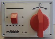
A
yellow cable from the Light socket
of the transformer is connected to the narrow side of the control panel. This
connection is a plug on the left of the console and a socket on the right.
These two connections are connected, i.e. they are equivalent. Three
wires lead from the three sockets on the rear of the control panel to the
three plug connections on the turntable: Ø red wire: voltage for
turning to the right, Ø grey wire: voltage for
unlocking, Ø red wire: voltage for
turning to the left. The
turntable receives the earth via the connected tracks; there is also an earth
plug at a slightly greater distance next to the aforementioned group of
three. |
|||
|
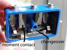
The
control panel with its two buttons contains a changeover switch and two
moment contacts. When
one of the two buttons on the control panel is pressed, an electromagnet
pulls back the lock and the motor of the turntable starts. If the button is
pressed further in, the rocker of the changeover switch may be tilted in this
direction and the direction of rotation reversed. |
|
||
|
As
long as a button is held down against the spring force, the latch of the
bridge remains retracted from the detent opening by an electromagnet. |
|
||
|
When
the button is released, the latch advances to the pit wall again and engages
in the next latching opening that passes by, at the next track connection. This
is the stop signal for the motor. If
you want to drive past a stop position, you must press the direction button
again in good time and hold it until after you have driven past. If
you remove the engine house, you can recognise the functions:
The
magnet (1) attracts the hand control lever (2), which is connected to the
bridge latch via rods (3). The
contact for the travelling current (4), which is closed in the process, is
located on the hand lever. This contact is adjustable. It must be closed when
the latch is in contact with the pit wall and open when the latch is in a
detent opening. Once
the bridge has started to move, the hand lever cannot return to its home
position because the latch cannot enter a detent opening at the edge of the
pit, but rubs against the wall of the pit. As
a result, the contact for the traction current remains closed until the latch
falls into the next detent opening. When
this happens, the traction current contact opens and the hook (5) stops the
gearbox, while the motor runs out disconnected by the slipping clutch (6). |
|||
|
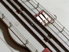
The
electrical connection from the pit to the bridge is made via five contact
rings, three sliding contacts can be seen on the bridge. The
centre conductors of the six shed tracks are switched off as long as the
bridge is not in front of them. The centre conductors of the four approach
tracks are connected to each other. |
|
||
|
This
means that the access track opposite one of the shed tracks cannot be used
without restriction, as the parked locomotive opposite would also be
travelling. This
results in... |
|||
|
Tracks
1 to 6 are the sidings, the shed tracks, which are only at the travelling
voltage when the bridge is in front of them. The
centre conductors of sidings 7 to 10 are connected ex works. If you have
different circuits at sidings 7 to 10, you must disconnect the connecting
cables under the turntable or insulate the centre conductor of the relevant
approach track at the edge of the turntable. |
|
||
|
If
a locomotive is driven onto the turntable via track 9, the centre conductor
of track 2 must be insulated from the turntable and supplied separately, as
the locomotive parked there would also run because the bridge is in front of
it. Tracks
7 and 10 as entry and exit have the advantage that the turntable can also be
crossed with longer shunting units. The same applies to tracks 9 and 2 if
track 2 is not used as a siding. If
you are planning a workshop track with a pit in the roundhouse, track 2 is
ideal for this. You can then use track 9 to push the defective locomotive
into the shed in a straight line with a shunting locomotive. If,
like me, you are planning a separate workshop shed, then tracks 7 and 10 are
suitable for the same reason: e.g. track 7 for the workshop shed and track 10
as an access track. A
large tender locomotive and a shunting locomotive will not fit on the
turntable bridge at the same time. The direct route is therefore
advantageous. Incidentally,
the prototype has a cable winch in the engine house of a turntable, which can
be used to pull unroadworthy locomotives out of the shed or into the shed via
a pulley. Maintenance: The
motor is identical in construction to the disc collector motors of the
locomotives of that time. Therefore,
see my page "Maintenance - clean, lubricate, replace". Faultless
operation depends on the condition of the contact rings and sliding contacts. |
|||
|
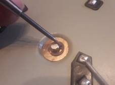
You
can simply remove the rotating bridge by loosening the locking ring on the
underside of the rotating axle. |
|
||
|
This
leaves the slip rings free for cleaning. |
|
||
|
You
can adjust and improve the preload, the contact pressure of the three sliding
contacts. |
|||
|
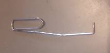
I
bent a small paper clip to do this. |
|
||
|
I
move the hook under the spring in the direction of the fastening rivet. This
pulls the spring up. Then
I press the angled end of the spring down with my finger so that the paper
clip gives it a slight bend. After
removing the paper clip, I push the spring back into its original position. |
|
||
|
It
now has a greater preload. Finally,
I clean the contact surfaces. Reassembly
should not be a problem. I report on the replacement of the original control panel and on
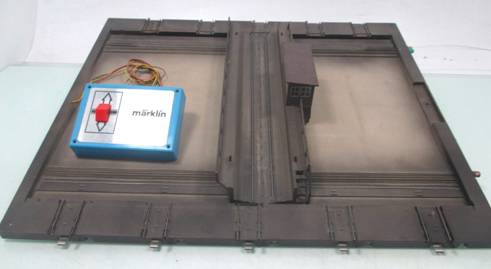
improvements to the operation and appearance of the disc mine HERE. The Fleischmann turntable as a Märklin version for the K-track As
I do not own such a turntable myself, I have to limit my text to information
I have received.
Variants: from
1991 to 2016: No. 7286 The
2-conductor version from Fleischmann is supposedly also suitable for the
Märklin system if the Märklin track connections are used (no guarantee). By
the way: The sky-facing windows have only existed since electric locomotives
were turned on the turntable. It is necessary to ensure that the pantographs
are retracted so that they do not get caught in the overhead line spider.
This turntable is therefore only correct from epoch 4 onwards. - However, the
engine house can be converted... Geometry: Outer
diameter 386 mm, bridge length 310 mm. The
scope of delivery includes 6 K-track connections, which can be mounted at
7.5° intervals as required. This results in 48 possible positions. Further
sidings in a set of 3: No. 7287. The
K-track turntable can also be used in M and C-track layouts with the help of
transition tracks, which are unfortunately only available as a straight piece
of track 180 mm long: Transition
track M - K : from 1969 no. 2191, from 1981 no. 2291 Due
to the design of this turntable, an opening must be cut in the table and sunk
into it. This means that the outgoing K tracks are then at table level. With
M or C tracks, they are sunk less deeply so that the top of the rails fit. Function: |
|||
|
The
analogue control panel allows you to select the direction of rotation and to
choose between single steps and continuous operation. |
|
||
|
The new turntable for the C-track As
I do not own this turntable, my knowledge is limited to the publicly
available ones.
Variants: Märklin
introduced a newly designed turntable in 2019 under the number 74861, available since 2021. Geometry: Diameter
378 mm, bridge length 263 mm. Grid
of possible exits: 12°, therefore not compatible with the previously
available roundhouses. Suitable
Märklin engine shed: No. 72886. Faller
locomotive shed to go with this set: No. 120281. Can
be extended up to 30 exits with extension set no. 74871. Due
to the design of this turntable, you have to cut an opening in the table and
sink it into it. The
C-track turntable can also be used in M and K-track layouts with the help of
transition tracks, which are unfortunately only available as a straight piece
of track 180 mm long: Transition
track K - C : from 1999 No. 24922 Note
on the K - C transition track section: On
my page "H0 track sections with
function" I show why these transition track sections should be
installed with care. Function: Exclusively
digitally controlled, but can also be driven on conventionally. The M-track transfer table As
I do not own this transfer table, my knowledge is limited to the publicly
accessible ones.
Variants: from
1979 to 2011: No. 7294 from
2012: 72941 There
is also a catenary set: From
2000 to 2003: No. 7295 Geometry: 360
x 420mm, M-track sidings, height of top of rail like the M-tracks. Only
two sidings are opposite each other, in the picture the ones on the right. For
the special position of the sidings see Märklin 0700 book page 7.2.015 The
M track transfer table can also be used in C and K track layouts with the aid
of transition tracks, which are unfortunately only available as a straight
piece of track 180 mm long: Transition
track M - C : from 1999 No. 24951 Note
on the transition track section M - K: On
my page "H0 track sections with
function" I show why these transition track sections should be
installed with care. Function: |
|||
|
The Prototype Märklin-H0-Knowledge Layout-Building Modelstock |
|||